Improving Predictability in Code Compliant High-Performance Wall Assemblies
Assemblies that reduce conductive attachment pathways tend to deliver more predictable performance, lower heat loss, and reduced moisture risk.
Continuous insulation (CI) is now widely recognized as a foundational strategy for improving the thermal performance of commercial buildings. Energy codes increasingly rely on CI to reduce heat flow through exterior walls. Yet despite its widespread adoption, CI often fails to deliver the level of performance designers expect once a building is built due to the impacts of multiple thermal bridging pathways.
The issue is not insulation thickness, but predictability of “real world” assembly performance. Fasteners, cladding attachment systems and structural supports routinely compromise the thermal control layer and can be difficult to account for those effects in a way that reflects real performance. Clear Field U‑Factor modeling helps close that gap by quantifying how wall assemblies perform once structural and cladding attachments are included.
Continuous Insulation in Code, and in Practice
The 2024 International Energy Conservation Code® (IECC) defines continuous insulation as insulation that is uncompressed and continuous across all structural members without thermal bridges other than fasteners and service openings.
Metal clips, rails, girts and thousands of fasteners commonly penetrate the thermal control layer in commercial assemblies. Each penetration creates a conductive pathway that allows heat to bypass the insulation, reducing installed performance significantly.
This gap matters beyond energy use. Reduced thermal performance increases heating and cooling loads, negatively impact occupant comfort, and raises the potential for moisture accumulation or condensation within the assembly.
For building safety professionals, these effects extend directly to durability, moisture management and indoor environmental quality.
Why R‑Value Alone Falls Short
Most specifications still rely on nominal insulation R‑values and overlook the cumulative impact of cladding attachments and fasteners.
U‑Factor provides a more complete measure. It captures overall heat transfer through the full wall assembly, accounting for materials, geometry, and major thermal bridges, like studs. Clear Field U‑Factor modeling incorporates the thermal bridging impact of fasteners and cladding attachment components, producing results that better align with installed conditions.
Structural Attachments and Thermal Bridging
In commercial wall assemblies, thermal bridging is primarily a structural issue. Cladding loads typically must be transferred through the enclosure to the primary structure which are often conductive metal components. As CI thickness increases, cladding is pushed farther from the structure, increasing structural demands and often driving more substantial attachment systems.
Each added structural element raises the potential for thermal de‑rating, widening the gap between designed and actual performance.
Cladding Design Over Continuous Insulation
Exterior cladding options are broad, but not all systems respond the same way when installed over CI. Heavier or more brittle claddings may require denser attachment strategies, while greater CI thickness can increase detailing complexity at openings and transitions.
To address these challenges, integrated wall systems have emerged, including insulated sheathing assemblies using plywood, OSB, magnesium oxide (MgO), fiberglass mat gypsum, fiber cement, or composite substrates, as well as insulated metal wall panels (IMWP) and architectural precast systems. While these approaches differ, their shared objective is reducing conductive load paths through the wall assembly.
Some systems incorporate air‑ and water‑resistive barriers into the sheathing; others offer fire‑resistive properties. Systems that minimize or eliminate metal sub‑girt assemblies are increasingly favored for their ability to reduce thermal bridging while simplifying detailing.
Clear Field Analysis and Performance‑Based Compliance
Clear Field U‑Factor analysis has moved into code practice. It is referenced in the Massachusetts Stretch Energy Code, which emphasizes performance pathways over prescriptive insulation requirements. In jurisdictions that adopt the Stretch Code, Clear Field analysis becomes part of the compliance framework.
Reference tools such as BC Hydro’s Thermal Envelope database provide examples of assemblies evaluated with thermal bridging considerations, offering additional guidance for performance‑based design and review.
The 2027 IECC approved a PSI and Chi factor table for thermal bridges in the component performance method (CEPC22-25, approved as modified 26-0 on 2/11/26), plus related changes at C402.1.4 and C402.1.2.1.6.
Case Study: Preserving Designed Thermal Performance
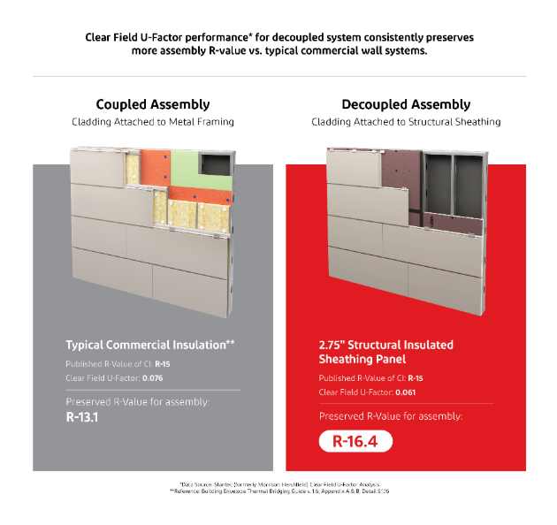
Clear Field modeling shows that assembly design can matter as much as insulation selection. When conventional commercial wall assemblies are evaluated at the whole‑assembly level, many preserve significantly less of their intended thermal value than expected.
To better understand these effects, DuPont engaged Stantec (previously Morrison Hershfield) to conduct third‑party Clear Field U‑Factor modeling across multiple wall assemblies with different attachment strategies. Assemblies can separate cladding attachment from framing preserved a higher percentage of their designed thermal value, reported up to approximately 93 percent, than comparable conventional assemblies once fasteners and sub‑framing were included.
An Illustrative Example
One example of a decoupled attachment approach is the DuPont™ ArmorWall™ System. The system combines structural sheathing with continuous insulation and an integrated air‑ and water‑resistive barrier. Cladding can be attached directly to the structural panel, reducing reliance on conductive metal sub‑framing.
The MgO‑faced insulated sheathing also supports fire‑resistive wall assemblies and can contribute to NFPA 285‑compliant, ignition resistance, and fire‑rated configurations where applicable. While ArmorWall™ is one implementation, it illustrates how attachment strategy directly influences thermal performance.
More Predictable Wall Performance
As energy codes advance, compliance is increasingly tied to assembly‑level performance rather than component values. The more relevant question is how much of the specified insulation value remains once the wall is built.
Clear Field U‑Factor analysis provides a practical way to answer that question. Assemblies that reduce conductive attachment pathways tend to deliver more predictable performance, lower heat loss, and reduced moisture risk. When air‑ and water‑resistive barriers are integrated, both conductive and convective heat transfer can be further reduced.
For building safety professionals, predictability matters. Wall assemblies that perform as modeled are easier to review, easier to approve, and more likely to meet their intended performance over the building’s service life.
About the Author

Tim Wilson is the Solutions Development Leader with the DuPont Building Knowledge Center, where he provides technical support for commercial construction projects throughout the United States and helps lead internal teams with new product development on the building envelope. Throughout his 22 years of industry experience, Tim has been involved in all facets of sales and marketing activities, including specifications development, educational seminars, field training, national advertising campaigns, commercialization of new building envelope products, and the integration of the Dow and DuPont product portfolios. Prior to joining DuPont, Tim was a quality control manager for a commercial general contractor and oversaw commercial projects in excess of $550 million.