Lead Structural Engineer Shares Insights on the Burj Khalifa, the World’s Tallest Structure
Larry Novak, Chief Structural Engineer for the Code Council, shares why this record-breaking structure is a significant achievement in terms of utilizing the latest design, codes, materials and construction technology and methods to provide an efficient, rational structure.
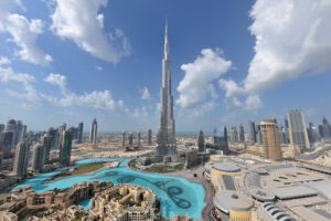
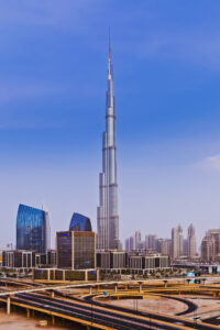
The goal of the Burj Khalifa Tower is not simply to be the world’s highest building; it is to embody the world’s highest aspirations.
During the six years and 22 million man-hours of construction to complete, the final height of the building was a “well-guarded secret”. At the opening ceremony on Jan. 4, 2010, the final height was revealed to be 828 meters (2,717 feet). This height “comfortably” exceeded the previous record holder, the 509-meter (1,671 feet) tall Taipei 101.
We are going to need a new word other than “skyscraper”. The Burj Khalifa doesn’t scrape the sky – it pierces it like a slender shiny needle, over half a mile high. The view from the top is more like looking out of a plane than a building.
Taking into consideration the curvature of the earth, one can see over 60 miles in all directions from the top of the spire on a clear day.
The 280,000-square-meter (3,000,000-square-foot) multi-use Burj Khalifa Tower is utilized for retail, a Giorgio Armani Hotel, residential and office space. The building has 700 residential apartments located from floors 45 to 108 and the remaining spaces till the 160th floor are occupied by the corporate officers.
The facts and figures about the tower are likewise surreal – like how it is 15 degrees Fahrenheit cooler at the top than at the bottom, or that you could watch the sunset at the ground level, then take the elevator up to the observation deck and watch the same sunset all over again. It is a new order of tallness.
Building Code and Structural Standards Applied to the Burj Khalifa
As with all super-tall projects, the construction of the Burj Khalifa met difficult structural engineering problems that needed to be addressed and resolved.
With safety in mind, building codes guard against unforeseen perils, including fires, earthquakes, electrical currents and more.
The current Dubai Building Code (DBC) was published in 2021 with the objective of unifying building design across Dubai.
Prior to the DBC being issued, the Dubai Municipality (DM) had specific regulations. Additionally, design teams and contractors relied on various documents to ensure their building projects meet the required standards. Generally, projects such as the Burj Khalifa, were designed and constructed in accordance with the requirements of the UAE Fire and Life Safety Code as well British Standards (BS) and American Codes and Standards.
For the design of the Burj Khalifa the following structural standards were applied:
- Reinforced Concrete Design Standard: The American Concrete Institute’s (ACI) ACI 318-02 Building Code Requirements for Structural Concrete was accepted by the DM as the basis of design for the reinforced concrete structure for the Burj Khalifa project.
- Structural Steel Design Standard: The structural steel spire was designed for gravity, wind, seismic and fatigue in accordance with the requirements of the American Institute of Steel Construction (AISC) Load and Resistance Factor Design Specification for Structural Steel Buildings (1999).
- Seismic Design Parameters: The DM specified Dubai as a Uniform Building Code UBC-97 Zone 2a seismic region with a seismic zone factor Z = 0.15 and soil profile Sc.
Architectural Design of the Burj Khalifa
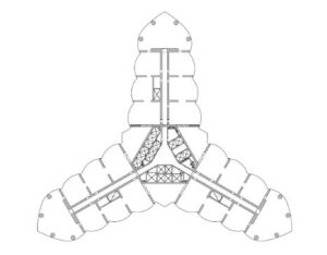
The context of the Burj Khalifa being located in the city of Dubai, UAE, drove the inspiration for the building form to incorporate cultural and historical particular to the region. The influences of the Middle Eastern domes and pointed arches in traditional buildings, as well as spiral imagery in Middle Eastern architecture, resulted in the tri-axial geometry of the Burj Khalifa and the tower’s spiral reduction with height.
The Y-shaped plan is ideal for residential and hotel usage, with the wings allowing maximum outward views and inward natural light.
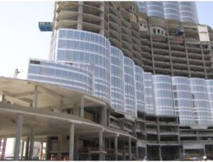
The exterior cladding is comprised of reflective glazing with aluminum and textured stainless steel spandrel panels and stainless-steel vertical tubular fins. Close to 26,000 glass panels, each individually hand-cut, were used in the exterior cladding of Burj Khalifa. The cladding system is designed to withstand Dubai’s extreme summer heat.
Burj Khalifa utilizes 57 elevators and eight escalators. The building service/fireman’s elevator has a capacity of 5,500 kg (12,100 pounds). Traveling at 10 meters per second (22 miles per hour), the observation elevators have the world’s longest travel distance from lowest to highest stop.
Structural System Description
The designers at Skidmore, Owings and Merrill (SOM) in Chicago purposely shaped the structural concrete Burj Khalifa – “Y” shaped – to reduce the wind forces on the tower, as well as to keep the structure simple and foster constructability. The structural system can be described as a “buttressed” core. Each wing, with its own high-performance concrete corridor walls and perimeter columns, buttresses the others via a six-sided central core, or hexagonal hub.
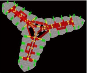
The result is a tower that is extremely stiff laterally and torsionally. SOM applied a rigorous geometry to the tower that aligned all the common central core, wall and column elements. This allows the construction to proceed without the normal difficulties associated with column transfers.
Over 200,000 cubic yards of concrete were required to construct the structure. This is enough to build a solid cube 180 feet on a side or a 700-mile-long sidewalk.
Outriggers at the mechanical floors allow the columns to participate in the lateral load resistance of the structure; hence, all the vertical concrete is utilized efficiently to support both gravity and lateral loads. The wall concrete specified strengths ranged from C60 to C80 cube strength (7,000 psi to 9,300 psi cylinder strength) and utilized a binary mix of Portland cement and fly ash.
The wall thickness and column sizes were fine-tuned to reduce the effects of creep and shrinkage on the individual elements which comprise the structure. Concrete creep is the continued deformation of a concrete structure under sustained load (basically, long-term pressure or stress on concrete can make it change shape).
To reduce the effects of differential column shortening (due to creep of the concrete) between the perimeter columns and interior walls, the perimeter columns were sized such that the self-weight gravity stress on the perimeter columns matched the stress on the interior corridor walls.
The five sets of outriggers, distributed up the building, tie all the vertical load-carrying elements together, further ensuring uniform gravity stresses; hence, reducing differential creep movements. Since the shrinkage in concrete occurs more quickly in thinner walls or columns, the perimeter column thickness of 600 mm (24 inches) matched the typical corridor wall thickness (similar volume to surface ratios) to ensure the columns and walls will generally shorten at the same rate due to concrete shrinkage.
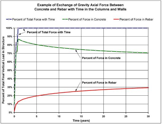
Due to the compatibility requirements of strain between the rebar and the concrete in a reinforced concrete column, as the concrete creeps and shrinks (i.e., shortens), the rebar must attract additional compressive stress and forces to maintain the same strain as the concrete. Since the total load is the same, over time, part of the load in a reinforced concrete column is transferred from the concrete to the rebar.
This unloading of the concrete, therefore, also reduces the creep in the concrete.
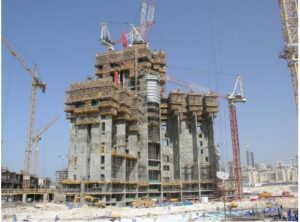
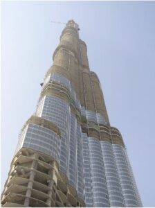
The crowning touch of Burj Khalifa is its telescopic spire. The structural steel spire was constructed from inside the building and jacked to its full height of over 200 meters (700 feet) using a hydraulic pump.
In addition to securing Burj Khalifa’s place as the world’s tallest structure, the spire is integral to the overall design, creating a sense of completion for the landmark, and also houses communications equipment.
Foundations and Site Conditions of the Burj Khalifa
If you want to build high, you must first dig deep.
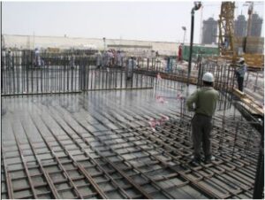
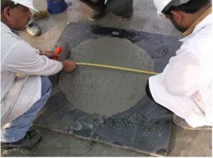
The groundbreaking of Burj Khalifa occurred in September 2004. The tower’s foundations consist of a pile-supported raft/mat. The solid reinforced concrete raft is 3.7 meters (12 feet) thick and was poured utilizing C50 cube strength (5,800 psi cylinder) self-consolidating concrete (SCC). The raft was constructed in four separate pours (three wings and the center core). Each raft pour occurred over at least a 24-hour period.
Wind Engineering
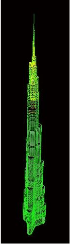
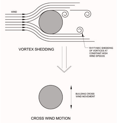
For a building of this height and slenderness, wind forces and the resulting motions in the upper levels become dominant factors in the structural design. An extensive program of wind tunnel tests and other studies were undertaken by Rowan Williams Davies and Irwin Inc.’s (RWDI) boundary layer wind tunnels in Guelph, Ontario.
The wind tunnel program included rigid-model force balance tests, full multi-degree-of-freedom aeroelastic model studies, measurements of localized pressures, pedestrian wind environment studies and wind climatic studies. Wind tunnel models account for the crosswind effects of wind-induced vortex shedding on the building.
In addition to the structural loading tests, the Burj Khalifa tower was studied by RWDI for cladding, pedestrian level and stack effect.
Based on the results of the aeroelastic models, the predicted building motions are within the ISO standard recommended values without the need for auxiliary damping.

Reaching New Heights with the Burj Khalifa
The world’s tallest structure, the Burj Khalifa, is a focal point of the overall development project, which includes shopping malls, hotels and residential buildings.
The architects and engineers utilized the latest in building codes and standards to develop the building form and the structural system, resulting in a tower that efficiently manages its response to the wind, while maintaining the integrity of the design concept.
It represents a significant achievement in terms of utilizing the latest design, codes, materials and construction technology and methods, to provide an efficient, rational structure to rise to heights never before seen.
The Burj Khalifa Project Team
- Owner: Emaar Properties PJSC
- Project Manager: Turner Construction International
- Architect/Structural Engineers/MEP Engineers: Skidmore, Owings & Merrill LLP
- Adopting Architect & Engineer/Field Supervision: Hyder Consulting Ltd.
- Independent Verification and Testing Agency: GHD Global Pty. Ltd.
- General Contractor: Samsung; BeSix; Arabtec
- Foundation Contractor: NASA Multiplex
References
- Baker, Korista, & Novak (2011), “Engineering the World’s Tallest – Burj Dubai”, paper in “The Broadview Anthology of Expository Prose, second edition”, Broadview Press, pp 643-653.
- Baker, Korista, Novak, Pawlikowski & Young (2007), “Creep & Shrinkage and the Design of Supertall Buildings – A Case Study: The Burj Khalifa Tower”, ACI SP-246: Structural Implications of Shrinkage and Creep of Concrete.
- Dubai Building Code, 2021 Edition, Published by the Government of Dubai.
- Irwin, Baker, Korista, Weismantle & Novak (2006), “The Burj Khalifa Tower: Wind Tunnel Testing of Cladding and Pedestrian Level”, Structure Magazine, published by NCSEA, November 2006, pp 47-50.