Code Corner: 2024 IPSDC Chapter 6: Soil Absorption Systems
The Code Corner explores sections of the International Codes® each month, focusing on key elements of these essential codes. This month, we’re spotlighting the scope of Chapter 6 of the 2024 International Private Sewage Disposal Code®.
The International Codes® (I-Codes®), developed by the International Code Council (ICC), are a family of fifteen coordinated, modern building safety codes that help ensure the design and construction of safe, sustainable and affordable structures.
The I-Codes are the most widely adopted set of model codes globally, implemented in all 50 U.S. states and many countries around the world.
The Building Safety Journal series, Code Corner, explores sections of the I-Codes each month, focusing on key elements of these essential codes. This month, we’re spotlighting the scope of Chapter 6 of the International Private Sewage Disposal Code® (IPSDC): Soil Absorption Systems.
2024 IPSDC Chapter 6: Soil Absorption Systems
The design of soil absorption systems depends heavily on the result of the tests and evaluation of the site soil conditions required in Chapter 4. Where soil is less permeable, the area of the soil absorption must be large compared to that required for highly permeable soils. The type of building that is being served by the private sewage disposal system also affects the size of the planned soil absorption area. Chapter 6 provides the methods for computing the required absorption area and details for the proper installation of the soil absorption systems.
A common misperception is that significant sewage treatment occurs in a septic tank. Another common misconception is that treatment occurs in the drain field pipe, panels or chambers. The reality is the treatment of the effluent occurs in the soil under the drain lines. The drain lines create a void in the soil to hold a manageable amount of effluent to ensure that the discharge of soil (by gravity or pressure) is consistent with the absorption rate of the soil, protecting against oversaturated soil resulting in ponding or effluent moving too rapidly to ground water. With its tested estimates of sewage amounts produced by various occupancies, this chapter provides guidance in properly sizing a drain field to ensure proper treatment of effluent.
605.1 Seepage trench excavations.
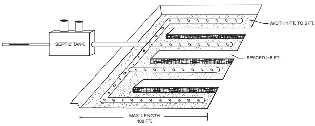
Seepage trench excavations shall be 1 foot to 5 feet (305 mm to 1524 mm) wide. Trench excavations shall be spaced not less than 6 feet (1829 mm) apart. The absorption area of a seepage trench shall be computed by using only the bottom of the trench area. The bottom excavation area of the distribution header shall not be computed as absorption area. Individual seepage trenches shall be not greater than 100 feet (30 480 mm) long, except as otherwise approved.
Drain field trench systems must be 1 to 5 feet wide and spaced greater than 6 feet apart. The drain field sizing must be calculated by using the bottom of the trench only; the sidewalls, top of the trench, and the header/manifold are not included. Each trench must not be longer than 100 feet except if stated in the approved design. See Commentary Figure 605.1.
To learn more about sewer management and how codes and standards can help, view ICC’s PMG Webpage.
To stay updated on the latest PMG industry news, subscribe to ICC’s PMG newsletter here.
About the Author

The International Code Council is a nonprofit association that provides a wide range of building safety solutions, including product evaluation, accreditation, certification, codification and training. It develops model codes and standards used worldwide to construct safe, sustainable, affordable and resilient structures.