CodeNotes: Fuel Gas Pipe Sizing
This CodeNotes resource provides an overview of fuel gas pipe sizing requirements in the 2021 International Codes.
This edition of CodeNotes —Fuel Gas Pipe Sizing— is based on the 2021 International Fuel Cas Code® and 2021 International Residential Code®.
Introduction
This CodeNotes™ provides an overview of fuel gas pipe sizing calculations and requirements in the 2021 International Fuel Gas Code® (IFGC®) and 2021 International Residential Code (IRC®). It will cover both the longest length method and the branch length method. Applicable code tables, figures and example problems and solutions are provided for each method to help the reader easily understand the pipe sizing methodology.
General Criteria and Related Information
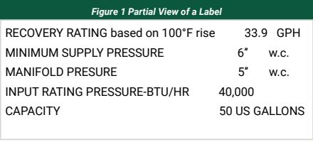
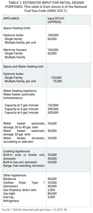
To determine the demand volume required by an appliance in cubic feet (m3) of gas per hour (CFH), the maximum input rating of the appliance must be used. This is provided by the appliance manufacturer in British thermal units per hour [Btu/h-(W)] as specified by the appliance manufacturer. If the average heating value per unit of fuel is known [about 1,000 Btu/ft3 (37.3 MJ/m3) for natural gas], the volume of gas required per hour can be calculated. The heating value can be obtained from the gas supplier. The IFGC requires the input rating of all appliances be shown on the appliance label. Figure 1 shows a typical example of a partial appliance label. When the input rating of the appliances is unknown at the time of the piping system design, the gas demand must be estimated based on input from appliance manufacturers, gas utilities or other sources, see Table 1: Estimated Input for Initial Design Purposes. The load on the piping system must be based on the simultaneous operation of all appliances at full output. While estimated input ratings can be used for initial system designs, pipe sizing must be verified once the actual appliances and their input ratings are known.
If a designer fails to verify the sizing with the actual connected load values, the resulting system could be undersized.
In all cases, the fuel gas supply piping must have the capacity to supply the actual connected load of the appliances installed.
IFGC Section 402.4.1/IRC Section G2413.4.1 Longest Length Method
These sections of the IFGC and IRC provide a step-by-step approach to the proper application of the respective code tables using the traditional longest-length method. Utilizing this method of pipe sizing, the pipe size of each section of gas piping in the system is determined using the longest length of piping from the point of delivery to the most remote outlet and the load of the section.
STEP 1: Determine Longest Length of Pipe
Determine the longest pipe run, which is the measured length of pipe from the point of delivery to the most remote gas outlet.
STEP 2: Determine Appliance Demand Volume
Determine the maximum gas demand volume required by each appliance in CFH (this is simply the appliance maximum input rate divided by the heating value of the gas). Note: Table 1 can be used where the input rates for appliances are not known. Add the maximum demand volume of all appliances connected to the system to obtain the maximum system load in CFH.
STEP 3: Select Appropriate Sizing Table
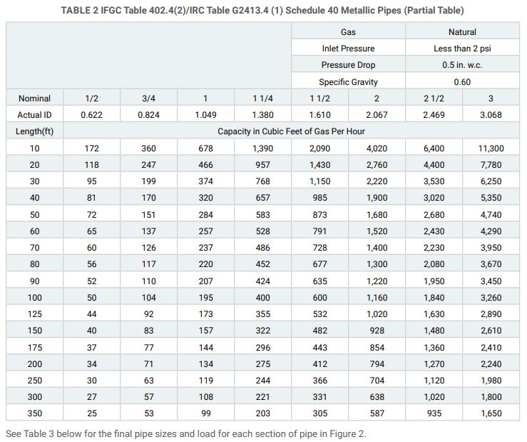
Determine the maximum gas demand volume required by Locate the appropriate sizing table, based on the type of pipe, gas, inlet pressure and pressure drop. See Table 2: IFGC Table 402.4(2)/IRC, Table G2413.4(1).
STEP 4: Gas Piping Sizing
Select the row in the table that equals the longest pipe length determined in Step 1 (if the longest length is between table values, use the row with the next higher value). This row is used to size all gas piping in the system.
For each appliance, select the column in that row that equals the appliance demand volume (if the value is between columns, select the column with the next larger value). Once the appropriate column is located, the required pipe size for that appliance can be found at the top of the table.
To size each section of pipe, add the gas demand for all appliances supplied through that section of pipe. Using the same table row as before, select the column in that row that equals the calculated demand volume for that section of pipe.
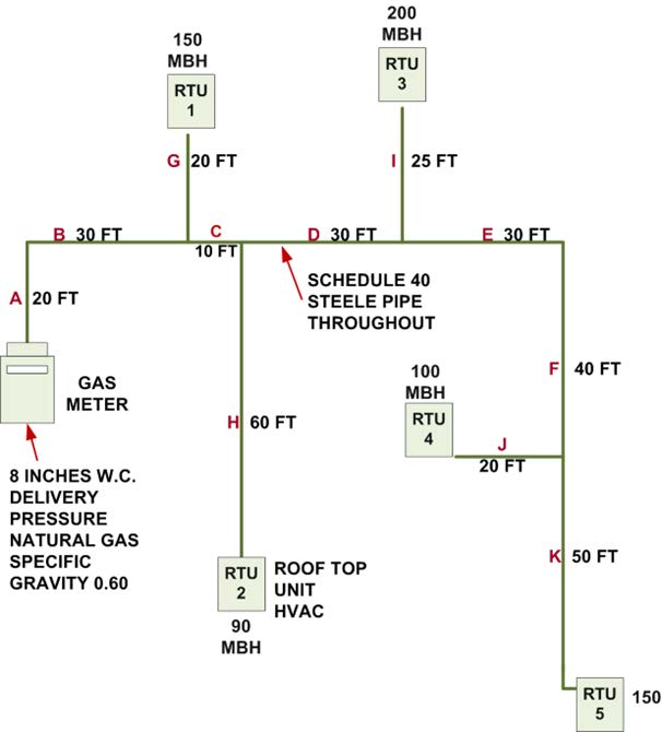
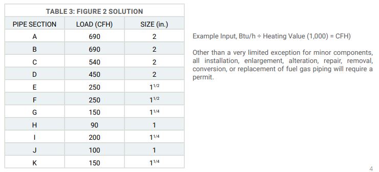
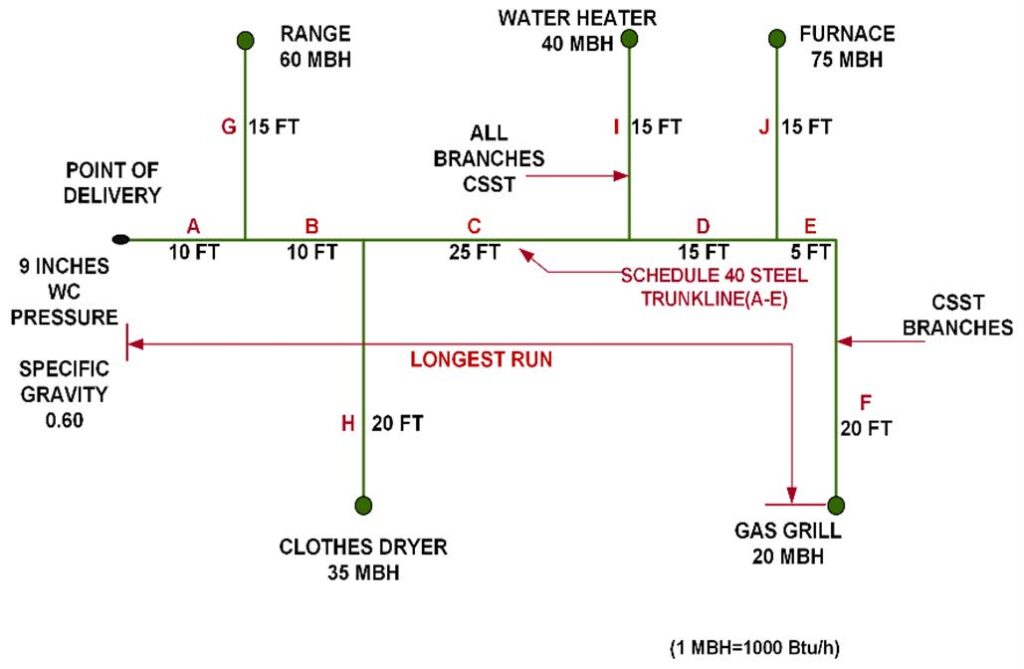
Longest Length Method Example. Using Schedule 40 Metallic Pipe (see Table 2), size the piping system shown in Figure 2. Solution: The longest run is from the meter (point of delivery) to rooftop unit (RTU) No. 5 and is 210 feet (64,008 mm). The result is that all pipe sizes will be chosen from the 250-foot (76,200 mm) row of the table. Determined sizes are shown in Table 3
A cubic feet per hour (CFH) is the quantity of gas flow in cubic feet, delivered during a time of one hour. It is calculated by dividing the appliance input with the fuel gas heating value. In our example, 1,000 Btu is the heating value used. The term MBH is commonly used in lieu of CFH to measure the quantity of gas flow in one hour. One MBH is equal to 1,000 Btu per hour.
IFGC Section 402.4.2/IRC Section G2413.4.2 Branch Length Method
This sizing method is a less conservative variation of the longest-length method. Whereas the longest-length method involves sizing all system piping based solely on the longest piping run length, this method involves sizing based on multiple piping lengths within the system.
As with the longest run method, the pipe size of each section of the longest pipe run from the point of delivery to the most remote outlet is determined using the table row for the longest run of piping and the load of the section of pipe.
The pipe size of all other branch piping, not sized as a section of the longest run, is determined using the table row for the length of piping from the point of delivery to the most remote outlet in each branch and the load of the section.
For SI: 1 inch = 25.4 mm, 1 foot = 304.8 mm, 1 pound per square inch = 6.895 kPa, 1 inch water column = 0.2488 kPa, 1 British thermal unit per hour = 0.2931 W, 1 cubic foot per hour = .0283 m3/h, 1 degree = 0.0 1745 rad.
Notes:
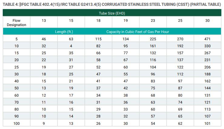
- Table includes losses for four 90-degree bends and two end fittings. Tubing runs with larger numbers of bends and/ or fittings shall be increased by an equivalent length of tubing to the following equation: L = 1.3n, where L is additional length (feet) of tubing and n is the number of additional fittings and/or bends.
- EHD—Equivalent Hydraulic Diameter, which is a measure of the relative hydraulic efficiency between different tubing sizes. The greater the value of EHD, the greater the gas capacity of the tubing.
- All table entries have been rounded to three significant digits.
IFGC Section 402.4.2 / IRC Section G2413.4.2
Item 1
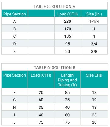
In accordance with Section 402.4.2 item 2/Section G2413.4.2, determine the size of Branch Sections A, B, C, D, and E (constructed of Schedule 40 steel pipe) based on the load of each section and the longest run length of 85 feet (25,908 mm). Because the system pressure is less than 0.5 psi (14 in. w.c.) (3.5 kPa), Table 4 is chosen. Because the longest run length is between rows in the table, the 90-foot (27,mm) row must be chosen.
Item 2
In accordance with Section 402.4.2 item 2/Section G2413.4.2, determine the size of Branch Sections F, G, H, I and J (constructed of CSST) based on the load of each section and the length of piping and tubing from the point of delivery to the outlet on that section. Table 4 is chosen because the branch sections are constructed of CSST, and the pressure is less than 0.5 psi [(14 in. w.c.) (3.5 kPa)]. Where a length falls between entries in the table, use the next longer length row. See Table 5 and Table 6 for the final pipe sizes and load section of pipe in Figure 3.
CSST is Corrugated Stainless Steel Tubing. It consists of continuous, semi-rigid stainless-steel tube with an outer yellow or black plastic jacket covering. Yellow-jacketed CSST was developed first and is the most common. It has a non-conductive plastic yellow jacket. Black-jacketed CSST is relatively new. Its black jacket is electrically conductive. Manufacturer information indicates this conductive jacket dissipates the energy of indirect lightning strikes that might otherwise pierce or damage the yellow-jacketed CSST.
About the Author

Charles Lee Clifton, retired senior director of plumbing, mechanical and fuel gas resources for the International Code Council, has more than 45 years of experience in the plumbing, mechanical and fuel gas industry. His career began as a second-generation plumber, working for his father at Clifton Plumbing Inc., in Tampa, Florida. He retired from the city of Los Angeles in 2007 as a principal inspector after 21 years of service. He retired from the International Code Council after 13 years of service.

Jim Cika, director, PMG technical resources for the International Code Council, where he serves as a subject matter expert to the plumbing, mechanical, and fuel gas codes. He represents ICC in federal and state coalitions, task forces, committees, and councils where expertise in I-Code subjects is required. Cika has more than 20 years of experience in the manufacturing and construction industry where he has served as chief technical expert for regulatory, product standards, building code and product engineering matters.

Gary has over 40 years of experience working within the Construction and Plumbing Industry. He is a seasoned Construction Project Manager as well as a Licensed Master Plumber in Massachusetts, New Hampshire, Maine and Vermont.
In addition, Gary holds an Unrestricted Construction Supervisor’s License (CSL) within the state of Massachusetts and completely understands the significance of code correlation. Lastly, while working with the International Code Council, he is currently an Adult Educational Master Plumbing & Fuel Gas Instructor and Continuing Education Instructor in the Commonwealth of Massachusetts.
Member of the International Code Council PMG Team responsible for developing, coordinating, directing and implementing programs to ensure the successful completion of the Government Relations goals and objectives as they apply to the International Plumbing Code, International Mechanical Code, International Fuel Gas Code, International Swimming Pool and Spa Code, and the International Private Sewage Disposal Code (and related services and programs of the International Code Council).