Methods of venting plumbing fixtures and traps in the 2021 International Plumbing Code
 The International Code Council is proud to distribute a helpful tool — Methods of Venting Plumbing Fixtures and Traps in the 2021 International Plumbing Code: Installation, Flexibility and Opportunity for Savings — to help expand your knowledge of the International Plumbing Code (IPC). The various approaches to venting that are permitted in the 2021 IPC are described in this handy reference tool authored by Lee Clifton, senior director of PMG resources at the Code Council. You will find that these venting provisions offer the installer and designer different paths to achieving an adequately vented system, which could result in cost savings along with ease of installation in different types of construction.
Chapter 9 of the IPC describes a variety of methods to vent plumbing fixtures and traps. The methods have been laboratory tested to determine sizing and installation requirements that provide proper venting to a drainage system. The venting methods have also been field-tested, establishing a long history of satisfactory service.
In this second of a four-part series of articles, we review “Alternative Venting Methods” addressed in the IPC, including island fixture venting, relief vents–stacks, air admittance valves and engineered vent systems.
Non-conventional venting methods
Proper application of these venting options can substantially reduce the amount of pipe and fittings used, while still providing proper venting. Inspectors and plumbers often overlook the opportunities afforded by these different venting methods, which have been proven to save money and may be helpful in areas where conventional venting methods may be difficult to install.
Island fixture venting
This is a specific method for venting an island sink, one limited to sinks and lavatories. Residential kitchen sinks with a dishwasher waste connection, a food waste grinder, or both, in combination with the kitchen sink waste, shall be permitted.
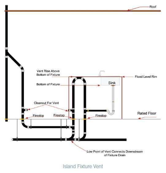 The island fixture vent shall connect to the fixture drain as required for an individual or common vent. The vent shall rise vertically to above the drainage outlet of the fixture being vented before offsetting horizontally or vertically downward. The vent or branch vent for multiple island fixture vents shall extend to a minimum of 6 inches (152 mm) above the highest island fixture being vented before connecting to the outside vent terminal.
The vent located below the flood level rim of the fixture being vented shall be installed as required for drainage piping in accordance with Chapter 7, except for sizing. The vent shall be sized in accordance with Section 906.2. The lowest point of the island fixture vent shall connect full size to the drainage system.
The connection shall be to a vertical drain pipe or to the top half of a horizontal drain pipe. Cleanouts shall be provided in the island fixture vent to permit rodding of all vent piping located below the flood level rim of the fixtures. Rodding in both directions shall be permitted through a cleanout.
As you can see from the diagram for this installation, this venting method provides for a free flow of air where liquid is not being trapped in the lowest portion of the vent, because of its connection to the drain. This method will work well in a crawl space or underground application.
Relief vents — Stacks of more than 10 branch intervals
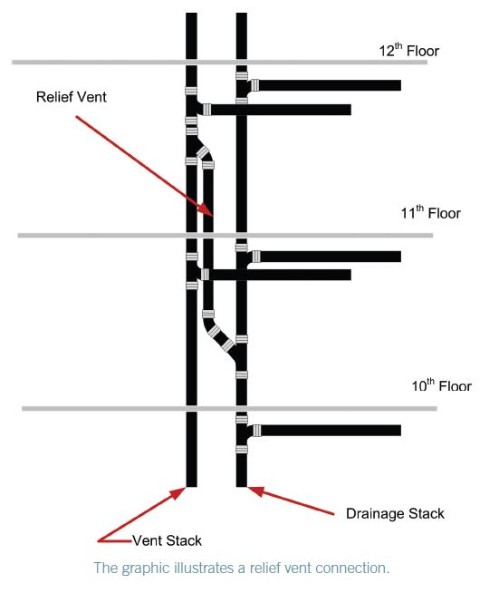 This venting method requires a relief vent equal to the size of the vent stack it connects with for buildings exceeding 10 branch intervals. A relief vent must be located at every 10 branch intervals, measured from the highest horizontal drainage branch, and then calculated downward to the base of the stack.
The lower end of the relief vent is connected to the soil or waste stack below the level of the horizontal branch that serves the floor level within the branch interval required to have the relief vent. The location of this connection is intended to allow waste that might get into the relief vent, including condensation, to reach a waste line. This connection is made using a wye fitting installed as a drainage fitting in order to not impair the flow. The upper connection of the relief vent is made to the vent stack and is to be located a minimum of 3 feet (914 mm) above the floor level of the same horizontal branch. This connection is made using a wye fitting installed in an inverted position. The required 3-foot (914 mm) minimum height required is a common theme in Chapter 9 and is intended to prevent waste flow from entering the vent stack.
Air admittance valves
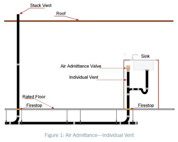 The air admittance valve (AAV) is a device designed to allow air to enter the drainage system to balance the pressure and prevent siphonage of the water trap when negative pressure develops in the system. In this way, it is used on individual vents, branch vents and circuit vents in lieu of terminating vents to the exterior of the structure. Stack vents and vent stacks are permitted to terminate to a stack type AAV. The exception is for stack vents or vent stacks that serve drainage stacks exceeding six branch intervals.
Because the AAV will not provide relief of positive pressures, there are certain installation requirements specified in the IPC to relieve positive pressure. The one open pipe vent required on every building drainage system in section 918.7 of the IPC, Vent Required, and section 904.1 of the IPC, Required Vent Extension, mandates that at least one vent pipe shall extend to the outdoors to relieve the system’s positive pressure. See Figure 1. Section 918.3.1, Horizontal Branches of the IPC, contains measures for pressure relief by requiring the installation of a relief vent where the horizontal branch is located more than four branch intervals from the top of the stack.
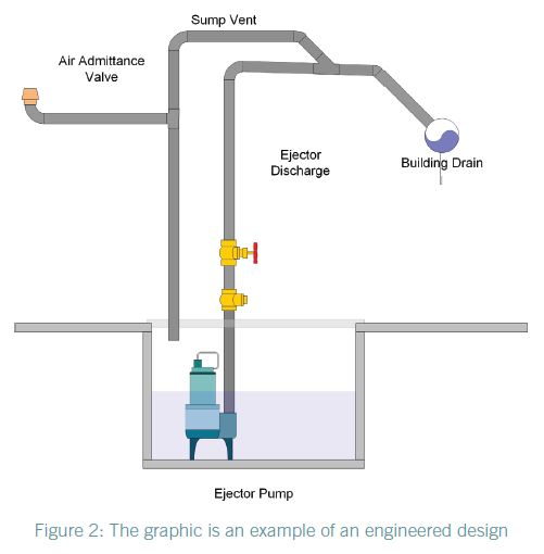 An AAV without an engineered design shall not be utilized to vent sumps or tanks of any type. Figure 2 shows an example of one manufacturer’s engineered design for use of an AAV on a sump.
An AAV has one moving part, a seal, which must be maintained a safe distance above the drain served. In the event of a drain stoppage, the seal may become inoperable or operate improperly if waste is permitted to rise into the AAV assembly.
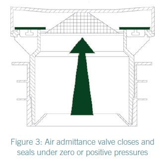
The AAV need not extend above the flood level rim of the fixture served because in the event of a drain blockage, the device will trap air between it and the rising waste, thereby protecting the device from contamination. The illustration of the AAV in Figure 3 is shown in the closed position. The valve is designed to close and seal under zero or positive pressure.
 AAV’s shall be installed in accordance with the requirements of section 918 and the manufactures instruction. The AAV’s shall be installed after the DWV testing required by Section 312.2 or 312.3 has been performed.
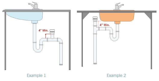
Individual and branch-type air admittance valves shall not be located not less than 4 inches (102 mm) above the horizontal branch drain or fixture drain being vented. (See Figure 4, Examples 1 and 2.)
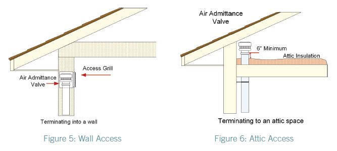
AAVs shall be accessible, should replacement be required. Such valves shall be installed in a location that allows air to enter the valve. Locating the valve in a sink or vanity cabinet is accessible. For in-wall installation, use a recess box/grill combination or access grill. See Figure 5.
The AAV shall be installed not less than 6 inches (152 mm) above insulation material. See Figure 6.
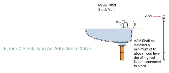
The stack-type AAV shall be located not less than 6 inches (152 mm) above the flood level rim of the highest fixture being vented. The AAV shall be located within the maximum developed length permitted for the vent. See Figure 7.
AAVs shall be accessible, should replacement be required. Such valves shall be installed in a location that allows air to enter the valve. The AAV shall be installed not less than 6 inches (152 mm) above insulation materials that may block air inlets or otherwise impair the operation of the device.
In summarizing, the installation of AAVs must conform to the requirements of section 918 of the IPC, Air Admittance Valves, or section P3113 of the IRC, Vent Pipe Sizing, and the manufacturers instruction. Where differences occur between the provisions of the code and the manufacturer instructions, the most restrictive provisions must apply.
Engineered vent systems
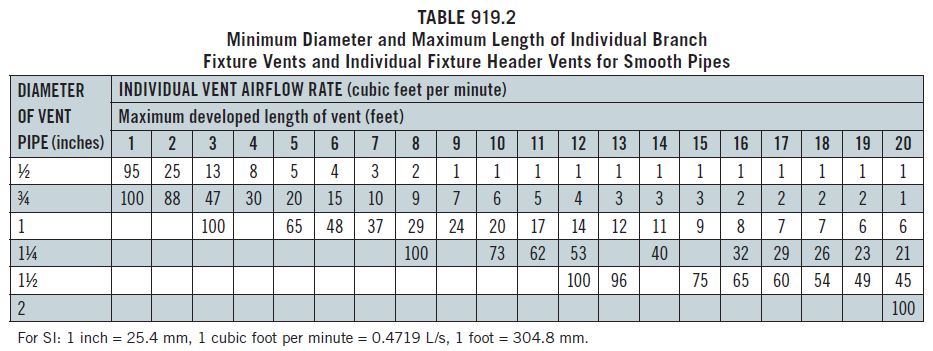
This type of venting system is considered to be an alternative engineered design. Notice that according to Table 919.2, which provides criteria for determining cubic feet or air flow per minute for various diameters of pipe, a vent can be as small as ½ inch in diameter.
After the individual vent airflow rate is determined by the equation in Section 919.2, the size and developed length are determined by Table 919.2. The values in the table indicate the maximum developed length for a given pipe size and the individual vent airflow rate. Note that the engineered vent system must be designed, signed and sealed by a registered design professional and will need to be submitted for review by the code official in accordance with Section 105 of the IPC.
About the Author

Charles Lee Clifton, retired senior director of plumbing, mechanical and fuel gas resources for the International Code Council, has more than 45 years of experience in the plumbing, mechanical and fuel gas industry. His career began as a second-generation plumber, working for his father at Clifton Plumbing Inc., in Tampa, Florida. He retired from the city of Los Angeles in 2007 as a principal inspector after 21 years of service. He retired from the International Code Council after 13 years of service.