CodeNotes: Gas Appliance Combustion, Ventilation and Dilution Air Part 1 – Outdoor Combustion Air Methods
This CodeNotes will focus on why the complete combustion of fuel gas is essential for the proper operation of gas-fired appliances and the methods for supplying all outdoor air.
This edition of CodeNotes — Gas Appliance Combustion, Ventilation and Dilution Air Part 1 – Outdoor Combustion Air Methods — is based on the 2021 International Residential Code® and the 2021 International Fuel Gas Code®.
Introduction
In the 2021 Internaitonal Residential Code® (IRC) and 2021 Internaitonal Fuel Gas Code® (IFGC) the methods of supplying combustion air range from simple (inherently more dependable) methods to more complex methods. There are five methods of providing combustion air:
- All indoor air
- All outdoor air
- Combination indoor and outdoor air
- Mechanical combustion air
- Engineered design
Air for combustion, ventilation, and dilution of flue gases for appliances installed in buildings are covered in the IFGC®, and for those buildings under the scope of the IRC®, it is addressed in the (IRC) Chapter 24, “Fuel Gas.” This CodeNote® uses a dual numbering system. The section numbers that appear in parentheses after each IRC section number are the section numbers of the corresponding text in the IFGC.
This CodeNotes® will focus on why the complete combustion of fuel gas is essential for the proper operation of gas-fired appliances and the methods for supplying all outdoor air. Combustion air is the total amount of air provided to the space that contains fuel-burning equipment (see Figure 1).
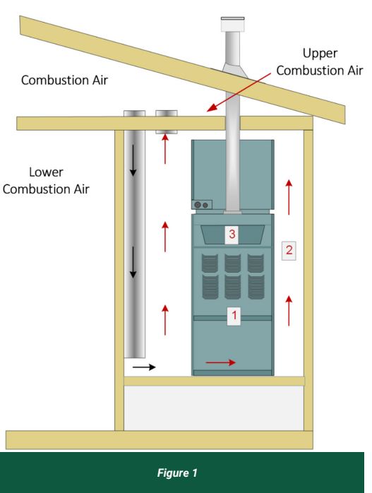
- Air for fuel Combustion
- Air for ventilation of equipment enclosure
- Air for draft air dilution
Although not implied in the term, combustion air also serves other purposes in addition to supplying oxygen. Combustion air ventilates and cools appliances and the rooms or spaces that enclose them. Combustion air also plays an important role in producing and controlling drafts in vents and chimneys. Depending on the appliance type, location, and building construction, supplying combustion air can either be easy or can involve complex designs and extraordinary methods.
Outdoor Combustion Air
Section G2407.6(304.6) describes two methods for supplying combustion air from the outdoors: the traditional method of two direct openings or ducts to the outdoors and a newer method using one opening or duct to the outdoors. Opening to spaces that are naturally ventilated with outdoor air, such as attics or crawl spaces, is considered as an acceptable alternative to a direct connection to the outdoors. These locations are only acceptable sources of combustion air when such spaces have adequate natural ventilation opening directly to the outdoors. Attic and crawl spaces ventilated by mechanical means are not an acceptable source of combustion air. When designing combustion air installations, the effect that openings to the outdoors can have on appliances, plumbing systems and building occupants must be considered. For example, depending on the location, openings to the outdoors can:
- Cause drafts that can blow out pilot lights or otherwise
interfere with appliance ignition and operation - Cause freezing of plumbing piping or other water-containing components
- Cause objectionable cold drafts that encourage the
occupants to block or cover openings
Installer Note: When installing combustion air openings remember that building occupants typically do not understand the need for, or the importance of, combustion air openings.criteria (LC-1023).
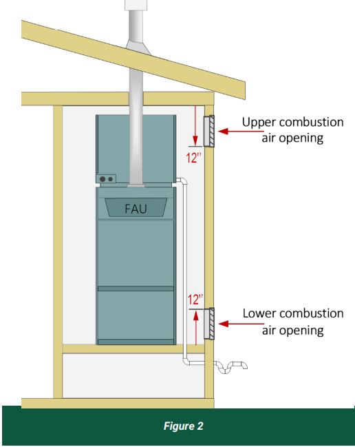
Two-permanent-openings Method
Section G2407.6.1(304.6.1) states that two permanent openings, one commencing within 12 inches (305 mm) of the top and one commencing within 12 inches (305 mm) of the bottom of the enclosure, shall be provided. The openings must communicate directly, or by ducts, with the outdoors or spaces that freely communicate with the outdoors. The minimum dimension of air openings can not be less than 3 inches (76 mm), because a long narrow opening is more easily blocked by leaves and lint than square openings (see Figure 2).
Two-permanent-openings Method With a Vertical Duct Installation
Where directly communicating with the outdoors, or where communicating with the outdoors through vertical ducts, each opening must have a minimum free area of 1 square inch per 4,000 Btu/h (550 mm ²Kw) of total input rating of all appliances in the enclosure. For example, a 60,000 Btu Forced Air Unit (FAU) requires 15 square inches (see Figure 3).

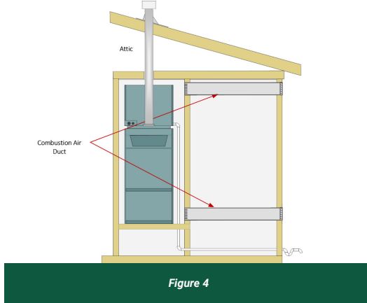
304.6.1 Two-Permanent-openings Method With a Horizontal Duct Installation
When communicating with the outdoors through horizontal ducts, each opening must have a minimum free area of not less than 1 square inch per 2,000 Btu/h (1,100 mm²Kw) of total input rating of all appliances in the enclosure. In this case, a 60, 000 Btu FAU requires 30 square inches (see Figure 4).
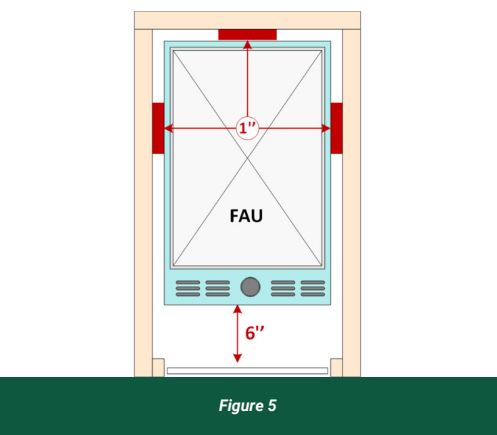
304.6.2 One-permanent-openings Method (Horizontal & Vertical)
Section G2407.6.2(304.6.2) requires that one permanent opening, commencing within 12 inches (305mm) of the top of the enclosure, shall be provided. The appliance must have a clearance of not less than 1 inch (25 mm) from the sides and back and 6 inches (152 mm) from the front of the appliance (see Figure 5).
The opening shall directly communicate with the outdoors, or through a vertical or horizontal duct, to the outdoors, or spaces that freely communicate with the outdoors and shall have a minimum free area of 1 square inch per 3,000 Btu/h (734mm²Kw) of the total input rating of all appliances located in the enclosure and not less than the sum of the area of all vent connectors in the space (see Figure 6).
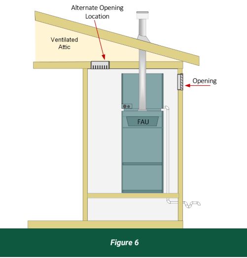
Installer Note: Research has shown that for modern appliances, a single opening to the outdoors will perform as well as the traditional two-opening method.
Conclusion
Adequate air supply is critical for properly operating all fuel-burning appliances. Compliance of the requirements of the IRC Chapter 24,” Fuel Gas”, and the IFGC must be adhered to in order to assure good operation. If this is accomplished, a more efficient and safer installation will result.
To view more CodeNotes documents, visit the International Code Council’s PMG website here.
About the Author

Jim Cika, director, PMG technical resources for the International Code Council, where he serves as a subject matter expert to the plumbing, mechanical, and fuel gas codes. He represents ICC in federal and state coalitions, task forces, committees, and councils where expertise in I-Code subjects is required. Cika has more than 20 years of experience in the manufacturing and construction industry where he has served as chief technical expert for regulatory, product standards, building code and product engineering matters.