

Tornado Mitigation
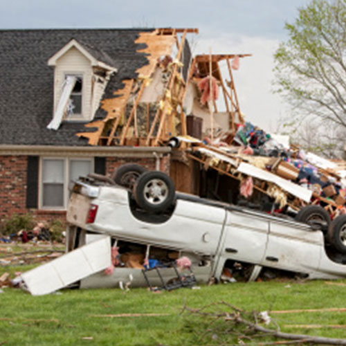
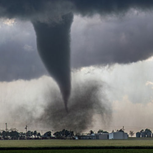
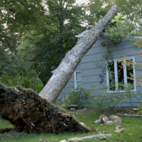
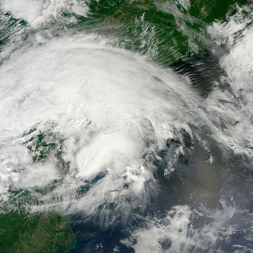
Tornadoes are powerful, rotating columns of air associated with severe thunderstorms and weather systems that move across land. Although tornadoes and derechos are generally smaller in scale than hurricanes and other major windstorms, their impacts can be equally devastating. Areas at risk for tornadoes extend well beyond the Great Plains, reaching across much of the continental United States.
Collectively, wind-related disasters are among the costliest natural hazards in the United States. Fortunately, the adoption and enforcement of modern building codes are helping communities become more resilient and recover more quickly after these events.
How Often Tornado Events Occur
Wind speeds associated with tornados can range from 58 mph to more than 200 mph, causing severe damage to the built environment in a matter of minutes.
According to the National Oceanic and Atmospheric Administration (NOAA), between 1991 and 2020, the U.S. averaged just over 268 tornadoes per year and saw a spike in 2024, with 536 tornadoes.
Tornado-Related Losses
According to Otero Property Adjusting and Appraisals, the annual cost of property damage from tornadoes often exceeds $400 million USD. The 2003 tornado in Moore, Oklahoma alone resulted in approximately $370 million USD of damage, according to the National Weather Service.
According to Otero Property Adjusting and Appraisals, the annual cost of property damage from tornadoes often exceeds $400 million USD. The 2003 tornado in Moore, Oklahoma alone resulted in approximately $370 million USD of damage, according to the National Weather Service.

Losses Avoided Through Building Codes and Mitigation
Modern building codes and hazard mitigation measures have proven to be some of the most effective tools for reducing damage from tornados. By incorporating stronger wind-resistant design requirements, improved roofing and opening protection, and more, communities can significantly reduce property damage, business interruption and recovery costs.
FEMA's Building Codes Save: A Nationwide Study found that adoption of the International Codes® (I-Codes®) could help communities avoid between $132 billion USD and $171 billion USD in cumulative losses through 2040, and $600+ billion USD by 2060.
Using the International Codes (I‑Codes) to Mitigate Tornado Hazards
The I-Codes, including the 2024 International Building Code® (IBC), International Residential Code® (IRC) and International Existing Building Code® (IBC), provide a comprehensive framework for the design, construction and retrofit of buildings to better withstand the effects of tornados. The codes establish minimum requirements that help protect life and property, reduce tornado-related damage and support faster community recovery following severe wind events.
The 2024 I-Codes address five broad areas:
- Wind Hazard Identification and Design Criteria: Requirements for determining design wind speeds, exposure conditions, risk categories and other factors used to establish wind loads for buildings and structures.
- Structural Resistance and Continuous Load Path: Provisions that ensure wind forces are transferred safely through the building’s structural system, including foundations, walls, roofs and connections.
- Building Envelope and Component Protection: Requirements for exterior walls, roofs, glazing, rooftop equipment and other building components to resist wind pressures, uplift forces and wind-driven rain.
- Storm Shelters and Critical Building Systems:Requirements for storm shelter design and construction, along with provisions that help protect life-safety systems and other critical building functions during severe wind events.
Key Tornado Provisions
Click book cover below to reveal/hide code sections.

International Existing Building Code®
Chapter 1 Scope and Administration
Section 104 Duties and Powers of Code Official
- 104.3.1 Determination of substantially improved or substantially damaged existing buildings and structures in flood hazard areas. For applications for reconstruction, rehabilitation, repair, alteration, addition or other improvement of existing buildings or structures located in flood hazard areas, the code official shall determine where the proposed work constitutes substantial improvement or repair of substantial damage. Where the code official determines that the proposed work constitutes substantial improvement or repair of substantial damage, the building is to meet the requirements of Section 1612 of the IBC, or Section R306 of the IRC, as applicable.
Section 106 Construction Documents
- 106.2.4 Exterior wall envelope. Construction documents for work affecting the exterior wall envelope shall describe the exterior wall envelope in sufficient detail to determine compliance with this code. The construction documents shall include manufacturer’s installation instructions that provide supporting documentation regarding maintaining the wind and weather resistance of the exterior wall envelope.
Chapter 2 Definitions
Chapter 2 provides definitions for terms used throughout the IEBC. These definitions provide a common language for designing buildings to resist severe wind events. While the IEBC incorporates the definitions found in the IBC, those terms that are unique to existing buildings can be found within Chapter 2 of the IEBC.
Chapter 3 Provisions for All Compliance Methods
Section 303 Storm Shelters
- 303.2 Addition to a Group E occupancy. Where an addition is made to an existing Group E occupancy located in an area where the shelter design wind speed for tornados is 250 mph and the occupant load of the addition is 50 or more, the addition requires a storm shelter constructed in accordance with ICC 500. There are a limited number of exceptions.
Chapter 4 Repairs
Section 405 Structural
- 405.2.3.1 Evaluation. Damaged buildings are to be evaluated by a registered design professional. The evaluation must establish whether the lateral force-resisting system of the damaged building, if repaired to its predamage state, would comply with the provisions of the IBC for load combinations that include wind effects.
- 405.2.3.3 Extent of repair for noncompliant buildings. If the evaluation does not establish that the lateral force-resisting system of the building in its predamage condition complies with the provisions of Section 405.2.3.1, then the lateral force-resisting system is to be retrofitted.
- 405.2.4.1 Lateral force-resisting elements. Regardless of the level of damage to vertical elements of the lateral force-resisting system, if substantial structural damage to gravity load-carrying components was caused primarily by wind, then the building is to be evaluated and, if noncompliant, it is to be retrofitted. There are a limited number of exceptions.
Chapter 5 Prescriptive Compliance Method
Section 502 Additions
- 502.4 Existing structural elements carrying lateral load. When an addition to an existing building is not structurally independent, the lateral force-resisting system of the existing building and its addition acting together as a single structure shall comply with the IBC. There are a limited number of exceptions.
Section 503 Alterations
- 503.4 Existing structural elements carrying lateral load. When an alteration to an existing building increases the design lateral loads, results in a prohibited structural irregularity as defined in ASCE 7 or decreases the capacity of any existing lateral load-carrying structural element, the lateral force-resisting system is required to meet the requirements of the IBC. There are a limited number of exceptions.
- 503.12 Roof diaphragms resisting wind loads in high-wind regions. When an alteration to an existing building requires a permit for reroofing and involves removal of roofing materials from more than 50% of the roof diaphragm in areas where the basic wind speed is greater than 130 mph, the roof diaphragms and its connections are to be evaluated for the wind loads specified in the IBC. When diaphragms and connections are not capable of resisting 75% of those wind loads, they are to be replaced or strengthened.
Section 506 Change of Occupancy
- 506.5.2 Snow and wind loads. Where a change of occupancy results in a building being assigned to a higher risk category, the building is required to satisfy the requirements of the IBC for the new risk category unless the area of the new occupancy is less than 10% of the building area.
Chapter 7 Alterations — Level 1
Section 706 Structural
- 706.3.2 Roof diaphragms resisting wind loads in high-wind regions. When reroofing involves removal of roofing materials from more than 50% of the roof diaphragm in areas where the basic wind speed is greater than 130 mph, the roof diaphragms and its connections are to be evaluated for the wind loads specified in the IBC. When diaphragms and connections are not capable of resisting 75% of those wind loads, they are to be replaced or strengthened.
Chapter 8 Alterations — Level 2
Section 805 Structural
- 805.3 Existing structural elements resisting lateral loads. When an alteration to an existing building increases the design lateral loads, results in a prohibited structural irregularity as defined in ASCE 7 or decreases the capacity of any existing lateral load-carrying structural element, the lateral force-resisting system is required to meet the requirements of the IBC. There are a limited number of exceptions.
Chapter 10 Change of Occupancy
Section 1006 Structural
- 1006.2 Snow and wind loads.
Where a change of occupancy results in a structure being assigned to a higher risk category, the structure is required to satisfy the requirements of the IBC for the new risk category unless the area of the new occupancy is less than 10% of the building area.
Chapter 11 Additions
Section 1103 Structural
- 1103.2 Lateral force-resisting system. When an addition to an existing building is not structurally independent, the lateral force-resisting system of the existing building and its addition acting together as a single structure shall comply with the IBC. There are a limited number of exceptions. When calculating demand-capacity ratios for wind, the code wind forces in effect at the time are to be utilized.
Chapter 14 Relocated or Moved Buildings
Section 1402 Requirements
- 1402.3 Wind loads. Relocated buildings are required to comply with IBC or IRC wind provisions, as applicable with only a few exceptions.
Chapter 15 Construction Safeguards
Section 1504 Protection of Pedestrians
- 1504.1.7 Adjacent to excavations. Barriers are to be capable of resisting wind pressure as specified in the IBC.
Appendix C Guidelines for the Wind Retrofit of Existing Buildings
Appendix C is intended to provide prescriptive methods for structural retrofitting of existing buildings to increase their resistance to wind loads. It is intended for voluntary use where the basic wind speed, V, is greater than 130 mph. The provisions of this chapter do not necessarily satisfy requirements for new construction.
International Residential Code®
Chapter 2 Definitions
Chapter 2 provides definitions for terms used throughout the IRC. These definitions provide a common language for designing buildings to resist severe wind events. They help us understand wind hazard intensity, determine the forces buildings must withstand, and describe the structural systems and connections needed to create a continuous load path. Together, they ensure that buildings are designed with appropriate safety factors, sturdier connections and stronger performance in high-risk areas.
Chapter 3 Building Planning
Chapter 3 contains a wide array of building planning requirements that are critical to designing a safe and usable building. This includes but is not limited to general structural design as it relates to wind. Examples of wind-related provisions include:
Section R301 Design Criteria
- R301.2.1 Wind design criteria Buildings and portions thereof shall be constructed in accordance with the wind provisions of the IRC using the ultimate design wind speeds provided. Additionally, where not otherwise specified, the wind loads provided are to be adjusted for height and exposure and are to be used to determine design load performance requirements for wall coverings, curtain walls, roof coverings, exterior windows, skylights, garage doors and exterior doors. The IRC also requires that a continuous load path be provided to transmit the applicable uplift forces from the roof assembly to the foundation.
- R301.2.1.1 Wind limitations and wind design required The wind provisions of the IRC do not apply to the design of buildings where the ultimate design wind speed equals or exceeds 140 mph There are a limited number of exceptions.
- R301.2.1.1.1 Sunrooms Sunrooms are required to comply with AAMA/NPEA/NSA 2100.
- R301.2.1.2 Protection of openings Exterior glazing in buildings located in windborne debris regions are required to be protected from windborne debris. This is accomplished by requiring that glazed opening be protected from windborne debris by meeting the requirements of the Large Missile Test of ASTM E1886 and ASTM E1996. Garage door glazed opening protection for windborne debris is required to be of an approved impact-resisting standard or ANSI/DASMA 115. The only exception to this is if wood structural panels are employed. A fastening schedule for wood structural panels is provided in table format.
- R301.2.1.3 Wind speed conversion The IRC provides a method of converting from nominal design wind speeds to ultimate design wind speeds in Table R301.2.1.3.
- R301.2.1.4 Exposure category The IRC requires that buildings be designed by considering each direction the wind approaches from and its corresponding exposure category adequately reflecting the characteristics of ground surface irregularities. The IRC also requires that account be taken of variations in ground surface roughness that arise from natural topography and vegetation as well as from constructed features. For any given wind direction, the exposure in which a specific building or other structure is sited shall be assessed as being one of the following categories: Exposure B (Urban and suburban areas), Exposure C (Open terrain with scattered obstructions) or Exposure D (Flat, unobstructed areas).
- R301.2.1.5 Topographic wind effects The IRC requires that areas having local historical data documenting structural damage to buildings caused by wind speed-up at isolated hills, ridges and escarpments are to be considered in the design of the building. In these designated areas, topographic wind effects shall apply only to buildings sited on the top half of an isolated hill, ridge or escarpment where the average slope of the top half of the hill, ridge or escarpment is 10% or greater and the hill, ridge or escarpment is 60 feet or greater in height for Exposure B, 30 feet or greater in height for Exposure C, and 15 feet or greater in height for Exposure D.
- R301.2.2.7 Height limitations The IRC sets limitations on wood-framed buildings to three stories above grade plane. Cold-formed steel-framed buildings are limited to less than or equal to three stories above grade plane. Structural insulated panel buildings are limited to two stories above grade plane.
Section R307 Storm Shelters
- R307.1 General This section applies to the design, construction and installation of storm shelters where constructed as either separate detached buildings or rooms or spaces within buildings for the purpose of providing protection from tornadoes and other severe windstorms.
Section R329 Solar Energy Systems
- R329.4.1.2 Wind load Rooftop-mounted photovoltaic panel or module systems and their supports are to be designed and installed to resist specified component and cladding loads.
Chapter 4 Foundations
Chapter 4 provides requirements for constructing footings and walls for foundations of wood, masonry, concrete and precast concrete. Namely a foundation’s ability to support the required design loads including the effects from wind loads. Examples of wind-related provisions include:
Section R404 Foundation and Retaining Walls
- R404.5.2 Precast concrete foundation design drawings The IRC requires that precast concrete foundation wall design drawings shall be submitted to the building official and approved prior to installation. These drawings are to include, at a minimum, the following information:
- Design loading as applicable.
- Footing design and material.
- Concentrated loads and their points of application.
- Soil bearing capacity.
- Maximum allowable total uniform load.
- Seismic design category.
- Basic wind speed.
Chapter 5 Floors
Chapter 5 provides the requirements for the design and construction of floor systems that will be capable of supporting minimum required design loads. Namely a floor’s ability to support the required design loads including the effects from wind loads. This chapter covers wood floor framing, wood floors on the ground and cold-formed steel floor framing. Examples of wind-related provisions include:
Section R502 Wood Floor Framing
- R502.12.4 Truss design drawings The IRC requires that truss design drawings are to be submitted to the building official and approved prior to installation. It also requires that the truss design drawings be provided with the shipment of trusses delivered to the job site and include, at a minimum, the following information:
- Slope or depth, span and spacing.
- Location of all joints.
- Required bearing widths.
- Design loads as applicable:
- 4.1. Top chord live load.
4.2. Top chord dead load.
4.3. Bottom chord live load.
4.4. Bottom chord dead load.
4.5. Concentrated loads and their points of application.
4.6. Controlling wind and earthquake loads.
- 4.1. Top chord live load.
Section R505 Cold-Formed Steel Floor Framing
- R505.1.1 Applicability limits The IRC provides provisions that control the construction of cold-formed steel floor framing for buildings and limits them to not greater than 60 feet in length perpendicular to the joist span, not greater than 40 feet in width parallel to the joist span and less than or equal to three stories above grade plane. Additionally, cold-formed steel floor framing is limited to sites where the ultimate design wind speed is less than 140 mph Exposure Category B or C.
- TABLE R505.3.1(1) The IRC also provides floor-to-foundation or bearing wall connection requirements in tabular form in TABLE R505.3.1(1).
Chapter 6 Wall Construction
Chapter 6 contains prescriptive provisions for the design and construction of walls. Namely a wall’s ability to support the required design loads including the effects from wind loads. The wall construction covered in Chapter 6 consists of five different types: wood framed, cold-formed steel framed, masonry, concrete and structural insulated panel (SIP). This chapter covers wood floor framing, wood floors on the ground and cold-formed steel floor framing. Examples of wind-related provisions include:
Section R602 Wood Wall Framing
- R602.3 Design and construction The IRC requires exterior walls of wood-frame construction to be designed and constructed in accordance with the prescriptive provisions of this chapter or in accordance with AWC NDS. It also requires that components of exterior walls and wall sheathing are to be fastened directly to framing members and, where placed on the exterior side of an exterior wall, to be capable of resisting the wind pressures.
These prescriptive requirements are listed in tabular format in TABLE R602.3(3) titled Requirements for Wood Structural Panel Wall Sheathing Used to Resist Wind Pressures.
- R602.3.5 Braced wall panel uplift load path The IRC requires that exterior wall panels that support roof rafters or trusses (including stories below top story) to have the framing members connected to resist gravity and wind uplift loads. These prescriptive requirements are listed in tabular format in the following tables:
- TABLE R602.10.3(1) BRACING REQUIREMENTS BASED ON WIND SPEED
- TABLE R602.10.6.4 TENSION STRAP CAPACITY FOR RESISTING WIND PRESSURES PERPENDICULAR TO METHODS PFH, PFG AND CS-PF BRACED WALL PANELS
Section R603 Cold-Formed Steel Wall Framing
The IRC provides prescriptive requirements regarding the use of cold-formed steel wall framing. The specific provisions can be found in the following tables:
- TABLE R603.3.1 WALL TO FOUNDATION OR FLOOR CONNECTION REQUIREMENTS
- TABLE R603.3.1.1(1) GABLE ENDWALL TO FLOOR CONNECTION REQUIREMENTS
- TABLE R603.3.2(1 - 16) 40-FOOT-WIDE BUILDING SUPPORTING TWO FLOORS, ROOF AND CEILING
- TABLE R603.3.2.1(1 - 2) ALL BUILDING WIDTHS GABLE ENDWALLS OVER 10 FEET IN HEIGHT
- TABLE R603.7(1 - 2) HEADER TO KING STUD CONNECTION REQUIREMENTS
- TABLE R603.8 HEAD AND SILL TRACK SPAN
- R603.9.4.1 Ultimate design wind speeds greater than 130 mph. The IRC also sets out additional limitations on these walls by specifying that when the ultimate design wind speeds exceed 130 mph for Exposure Category C, the walls are to be provided with direct uplift connections.
Section R606 General Masonry Construction
- R606.4.4 Parapet walls The IRC provides prescriptive requirements on unreinforced solid masonry parapet walls that are not less than 8 inches thick, and their height is not to exceed four times their thickness. Similarly, unreinforced hollow unit masonry parapet walls are to be not less than 8 inches thick, and their height shall not exceed three times their thickness.
Section R607 Glass Unit Masonry
- R607.4.1 Exterior standard-unit panels The IRC establishes a maximum area of each individual standard-unit glass masonry panel of 144 square feet where the design wind pressure is 20 pounds per square. It also sets the maximum panel dimension between structural supports at 25 feet in width or 20 feet in height.
Section R608 Exterior Concrete Wall Construction
- R608.2 Applicability limits The prescriptive provisions of this section apply to the construction of exterior concrete walls for buildings not greater than 60 feet in plan dimensions, floors with clear spans not greater than 32 feet and roofs with clear spans not greater than 40 feet and Buildings not exceeding 35 feet in mean roof height or two stories in height above grade. Additionally, walls constructed in accordance with the provisions of this section are limited to a maximum design wind speed of 160 mph Exposure B, 136 mph Exposure C and 125 mph Exposure D.
- R608.6.2 Wall reinforcement for wind The prescriptive requirements of this section state that vertical wall reinforcement for resistance to out-of-plane wind forces is to be determined using Tables R608.6(1), R608.6(2), R608.6(3) or R608.6(4). For the design of nonload-bearing walls, Tables R608.6(1), R608.6(2) and R608.6(3) are to be used.
Additionally, there are to be a vertical bars at corners of exterior walls with a minimum horizontal reinforcement of four No. 4 bars [Grade 40 (280 MPa)] placed as follows: top bar within 12 inches (305 mm) of the top of the wall, bottom bar within 12 inches (305 mm) of the finish floor and one bar each at approximately one-third and two-thirds of the wall height.
Section R609 Exterior Windows and Doors
- R609.2 Performance The IRC requires that exterior windows and doors are to be capable of resisting design wind loads adjusted for height and exposure.
- R609.4.1 Garage door labeling Garage doors are to be labeled with a permanent label provided by the garage door manufacturer that identifies the garage door manufacturer, the garage door model/series number, the positive and negative design wind pressure rating, the installation instruction drawing reference number and the applicable test standard.
- R609.6 Windborne debris protection. The IRC requires that all exterior windows, glass doors and doors with glass in buildings located in windborne debris regions are to be protected against windborne debris.
Chapter 7 Wall Covering
Chapter 7 establishes the various types of materials, materials standards and methods of application permitted as interior and exterior wall coverings. Exterior wall coverings regulated by this section include aluminum, stone and masonry veneer, wood, hardboard, particleboard, wood structural panel siding, wood shakes and shingles, exterior plaster, steel, vinyl, fiber cement and exterior insulation finish systems. This chapter also contains requirements relating to wind resistance for exterior wall coverings. Examples of wind-related provisions include:
Section R703 Exterior wall Covering
- R703.1.2 Wind resistance The IRC requires that exterior wall coverings, siding, exterior soffit and backing materials and their attachments are to be capable of resisting wind loads.
- R703.3.2 Wind limitations Among the limitations for the IRC’s prescriptive requirements, when the design wind pressure exceeds 30 psf, the attachment of wall coverings is to be designed to resist component and cladding loads for walls and adjusted for height and exposure. The prescriptive attachment requirements are tabularized into TABLE R703.11.2 title Required Minimum Wind Load Design Pressure Rating for Vinyl Siding Installed Over Foam Plastic Sheathing Alone.
Section R703 Exterior wall Covering
- R704.1 General wind limitations Among the IRC’s limitations, when the design wind pressure exceeds 30 psf, the attachment of exterior soffits is to comply with the design wind pressure determined using the component and cladding loads for walls using an effective wind area of 10 square feet and adjusted for height and exposure.
- R704.3.1 Vinyl exterior soffit panels When the exterior soffit panels are vinyl, their attachments are to be capable of resisting wind loads for walls using an effective wind area of 10 square feet and adjusted for height and exposure and installed using fasteners specified by the manufacturer. They are also to be fastened at both ends to a supporting component such as a nailing strip, fascia or subfascia component. Where the unsupported span of exterior soffit panels is greater than 12 inches, intermediate nailing strips are to be provided.
- R704.3.2 Fiber-cement exterior soffit panels. When the exterior soffit panels are Fiber-cement, their attachments are to be capable of resisting wind loads for walls using an effective wind area of 10 square feet and adjusted for height and exposure and installed using fasteners specified by the manufacturer.
- R704.3.3 Hardboard exterior soffit panels. When the exterior soffit panels are Hardboard, their attachments are to be capable of resisting wind loads for walls using an effective wind area of 10 square feet and adjusted for height and exposure and installed using fasteners specified by the manufacturer.
- R704.3.4 Wood structural panel exterior soffit. When the exterior soffit panels are structural wood, their attachments are to be capable of resisting wind loads for walls using an effective wind area of 10 square feet and adjusted for height and exposure and installed using fasteners specified by the manufacturer.
Chapter 8 Roof-Ceiling Construction
Chapter 8 addresses the design and construction of roof-ceiling systems. This chapter contains two roof-ceiling framing systems: wood framing and cold-formed steel framing. This chapter also contains requirements relating to wind resistance for these systems. Examples of wind-related provisions include:
Section R802 Wood Roof Framing
- R802.10.1 Truss design drawings. The IRC requires that truss design drawings are to be submitted to the building official and approved prior to installation. It also requires that the truss design drawings be provided with the shipment of trusses delivered to the job site and include, at a minimum, the following information:
- Slope or depth, span and spacing.
- Location of all joints.
- Required bearing widths.
- Design loads as applicable:
- 4.1. Top chord live load.
4.2. Top chord dead load.
4.3. Bottom chord live load.
4.4. Bottom chord dead load.
4.5. Concentrated loads and their points of application.
- 4.1. Top chord live load.
- R802.10.2.1 Applicability limits The IRC provides provisions that control the construction of wood roof framing for buildings and limits them to not greater than 60 feet in length perpendicular to the joist span, not greater than 36 feet in width parallel to the joist span and less than or equal to three stories above grade plane. Additionally, wood roof framing is limited to sites where the ultimate design wind speed is less than 140 mph for Exposure Category B or C.
- R802.11 Roof tie uplift resistance The IRC requires that roof assemblies be provided with uplift resistance based on the design wind loads. Exceptions include rafters or trusses that are attached to their supporting wall assemblies where the uplift force per rafter or truss does not exceed 200 pounds or where the basic wind speed does not exceed 115 mph for exposure category B and the roof pitch is 5 units vertical in 12 units horizontal or greater. The values for rafter or truss uplift connection forces from wind can be found in TABLE R802.11.
- R802.11.1 Truss uplift resistance The IRC requires that roof trusses be attached to supporting wall assemblies by connections capable of resisting uplift forces as specified on the truss design drawings for the ultimate design wind speed.
Section R804 Cold-Formed Steel Roof Framing
- R804.1.1 Applicability limits. The IRC provides provisions that control the construction of cold-formed steel roof framing for buildings and limits them to not greater than 60 feet in length perpendicular to the joist span, not greater than 40 feet in width parallel to the joist span and less than or equal to three stories above grade plane. Additionally, cold-formed steel roof framing is limited to sites where the ultimate design wind speed is less than 140 mph for Exposure Category B or C. Roof framing fastening schedules can be found in TABLE R804.3.
Chapter 9 Roof Assemblies
Chapter 9 addresses the design and construction of roof assemblies. A roof assembly includes the roof deck, substrate or thermal barrier, insulation, vapor retarder and roof covering. Among other requirements, this chapter identifies the requirement for wind resistance of roof coverings. The types of roof covering materials and installation addressed by Chapter 9 are: asphalt shingles, clay and concrete tile, metal roof shingles, mineral-surfaced roll roofing, slate and slate-type shingles, wood shakes and shingles, built-up roofs, metal roof panels, modified bitumen roofing, thermoset and thermoplastic single-ply roofing, sprayed polyurethane foam roofing, liquid applied coatings and building-integrated photovoltaic (BIPV) roof coverings. Examples of wind-related provisions include:
Section R905 Requirements for Roof Coverings
The IRC specifies requirements for roof underpayments in the following tables:
- TABLE R905.1.1(1) UNDERLAYMENT TYPES
- TABLE R905.1.1(2) UNDERLAYMENT APPLICATION
- TABLE R905.1.1(3) UNDERLAYMENT ATTACHMENT
- R905.2.4.1 Wind resistance of asphalt shingles. The IRC requires that asphalt shingles shall be tested in accordance with ASTM D7158and that they meet specific classification requirements relating to the appropriate ultimate design wind speed. The IRC also requires that asphalt shingle packaging bears a label to indicate compliance with ASTM D7158.
- R905.3.6 Wind resistance of concrete and clay tile. In regions where wind design is required the IRC requires that wind loads on concrete and clay tile are to be determined.
- R905.4.4.1 Wind resistance of metal roof shingles. The IRC requires that metal roof shingles fastened to wood structural panels, solid lumber sheathing or closely fitted lumber sheathing are to be tested in accordance with ASTM D3161, FM 4474, UL 580 or UL 1897 for the appropriate maximum basic wind speed. Additionally, metal shingle packaging is to bear a label indicating compliance with ASTM D3161.
- R905.5.6 Wind resistance of mineral-surfaced roll roofing. The IRC requires that mineral-surfaced roll roofing shall be installed to resist the component and cladding wind loads adjusted for height and exposure.
- R905.6.5 Wind resistance of slate shingles. The IRC requires that slate shingles are to be tested in accordance with ASTM D3161 and its packaging is to bear a label indicating compliance with ASTM D3161.
- R905.7.5 Wind resistance of wood shingles. In regions where wind design is required the IRC requires that wood shingles are to be installed to resist the component and cladding wind loads and adjusted for height and exposure.
- R905.8.6 Wind resistance of wood shakes. In regions where wind design is required the IRC requires that wood shakes are to be installed to resist the component and cladding wind loads and adjusted for height and exposure.
- R905.9.4 Wind resistance of built-up roofs. In regions where wind design is required the IRC requires that Built-up roof coverings are to be installed to resist the component and cladding wind loads and adjusted for height and exposure.
- R905.10.5 Wind resistance of metal roof panels. In regions where wind design is required the IRC requires that metal roof panels are to be installed to resist the component and cladding wind loads and adjusted for height and exposure. In cases where metal roof panels are applied to a solid or closely fitted deck they are to be tested for wind resistance as appropriate and with a limited number of exceptions.
- R905.11.4 Wind resistance of modified bitumen roofing. In regions where wind design is required the IRC requires that Modified bitumen roofing is to be installed to resist the component and cladding wind loads and adjusted for height and exposure.
- R905.12.4 Wind resistance of single-ply roofing.
In regions where wind design is required the IRC requires that Single-ply roofing is to be installed to resist the component and cladding wind loads and adjusted for height and exposure. - R905.13.4 Wind resistance of sprayed polyurethane foam roofing. In regions where wind design is required the IRC requires that Sprayed polyurethane foam roofing is to be installed to resist the component and cladding wind loads and adjusted for height and exposure.
- R905.14.4 Wind resistance of liquid-applied roofing. In regions where wind design is required the IRC requires that Liquid-applied roofing is to be installed to resist the component and cladding wind loads and adjusted for height and exposure.
International Building Code®
Chapter 2 Definitions
Chapter 2 provides definitions for terms used throughout the IBC. These definitions provide a common language for designing buildings to resist severe wind events. They help us understand wind hazard intensity, determine the forces buildings must withstand and describe the structural systems and connections needed to create a continuous load path. Together, they ensure that buildings are designed with appropriate safety factors, sturdier connections and stronger performance in high-risk areas.
Chapter 4 Special Detailed Requirements Based on Occupancy and Use
Section 423 Storm Shelters: This entire section applies to the design and construction of storm shelters constructed as separate detached buildings or constructed as rooms or spaces within buildings for the purpose of providing protection from tornadoes, hurricanes and other severe windstorms during the storm. This section specifies where storm shelters are required and provides requirements for the design and construction of storm shelters.
- 423.2 Construction – storm shelters are to be constructed in accordance with this code and ICC 500 and shall be designated as hurricane shelters, tornado shelters or combined hurricane and tornado shelters.
- 423.3 Occupancy classification – occupancy classifications for storm shelters are determined based on whether the shelter is a dedicated storm shelter, a storm shelter within a host building, its design occupancy load and its location relative the building(s) it services.
Chapter 9 Fire Protection and Life Safety Systems
Section 909 Smoke Control Systems
- 909.4.1 Smoke control – stack effect. Smoke control system is designed so normal or reverse stack effect doesn't interfere is the system's capabilities.
- 909.4.3 Smoke control – wind effect. Smoke control system design considers adverse wind effects.
- 909.20.4 Smoke control - stairway and ramp pressurization. Pressurization relative to stairway and ramp
Section 913 Fire Pumps
- 913.2 Fire pumps – interruption of service. Protection of fire pump, driver and controller against service interruption through damage caused by windstorm, flood and other special weather and environmental conditions.
Chapter 10 Means of Egress
Section 1031 Emergency Escape and Rescue
- 1031.2 Where required – storm shelter exception. Storm shelters are excepted to include emergency escape and rescue openings.
Chapter 11 Accessibility
Section 1112 Signage
- 1112.5.2 Variable message signs – emergency shelters. Emergency shelters must provide variable message signage conveying emergency-related information.
Chapter 14 Exterior Walls
Section 1402 Performance Requirements
- 1402.3 Performance requirements - wind resistance. Exterior walls and coverings, soffits and associated openings designed to resist superimposed loads.
Section 1404 Installation of Wall Coverings
- 1404.12.1 Attachment. Exterior metal veneer attachment fastenings and their spacing designed to resist wind loads specified in Section 1609.
- 1404.15 Vinyl siding and insulated vinyl siding - design wind pressure requirements. Vinyl siding permitted on exterior walls where the design wind pressure does not exceed 30 psf., or else compliance with Chapter 16.
- 1404.15.2 Installation over foam plastic insulated sheathing - design pressure requirements. Vinyl siding over foam plastic sheathing to comply with Section 1404.15 and have wind load design pressure rating in accordance with Table 1404.15.2.
- 1404.17 Fiber cement siding. Fiber-cement siding permitted on exterior walls for wind pressure resistance or basic wind speed exposures as indicated by the manufacturer's listing and installation instructions.
- 1404.18 Polypropylene siding. Polypropylene siding is limited to exterior walls in areas meeting maximum basic wind speeds specified in Chapter 16, with building height considerations.
Section 1406 Metal Composite Material (MCM)
- 1406.4 Structural design. Metal composite materials designed and constructed to resist wind loads as required by Chapter 16 for components and cladding.
- 1406.5 Approval. Results of approved tests or engineering analysis to be submitted to the building official for compliance verification with Chapter 16 for wind loads.
- 1406.6 Weather resistance. MCM systems must be designed and constructed to resist wind and rain in accordance with this section and manufacturer's installation instructions.
Section 1407 Exterior Insulation and Finish Systems (EIFS)
- 1407.3 Structural design. Underlying structural framing and substrate to be designed and constructed to resist loads as required by Chapter 16.
- 1407.4 Weather resistance. System designed and constructed to resist wind and rain in accordance with this section and manufacturer's application instructions.
Section 1408 High-Pressure Decorative Exterior-Grade Compact Laminates (HPL)
- 1408.4 Structural design. HPL system to be designed and constructed to resist wind loads as required by Chapter 16 for components and cladding.
- 1408.5 Approval. Results of approved tests or engineering analysis to be submitted to the building official for compliance verification with Chapter 16 for wind loads.
- 1408.6 Weather resistance. HPL systems must be designed and constructed to resist wind and rain in accordance with this section and manufacturer's installation instructions.
Section 1409 Insulated Metal Panel (IMP)
- 1409.2 Structural design. Structural design of IMP system to be in accordance with this section.
- 1409.3 Weather resistance. IMP systems must be designed and constructed to resist wind and rain in accordance with this section and manufacturer's installation instructions
Section 1412 Soffits and Fascias at Roof Overhangs
- 1412.2 General wind requirements. Soffits and fascias capable of resisting components and cladding loads for walls in accordance with Chapter 16 using an effective wind area of 10 square feet.
- 1412.3 Vinyl & aluminum soffit panels. Vinyl and aluminum soffit panels to meet fastener and installation instruction requirements based on required design wind pressures.
- 1412.5 Hardboard soffit panels. Hardboard soffit panel minimum thickness and installation instruction requirements to meet required design wind pressures.
- 1412.7 Aluminum fascia. Aluminum fascia to meet minimum thickness and manufacturer's installation instruction requirements.
Chapter 15 Roof Assemblies and Rooftop Structures
Section 1504 Performance Requirements
- 1504.1 Wind resistance of roofs. Roof decks and roof coverings to be designed in accordance with Section 1504.
- 1504.2 Wind resistance of asphalt shingles. Asphalt shingles tested to ASTM D7158 and meet classification requirements of Table 1504.2 for maximum basic wind speed.
- 1504.3 Wind resistance of clay and concrete tile. Wind loads on clay and concrete tile roof coverings to be in accordance with Section 1609.6.
- 1504.4 Wind resistance of nonballasted roofs (includes built-up, modified bitumen, fully adhered/mechanically attached, metal shingles, metal panels, and slate). Roof coverings mechanically attached to the roof deck to be designed to resist design wind load pressures with Section 1609.6.2.
- 1504.5 Ballasted low-slope single-ply roof systems. Ballasted low-slope single-ply roof system coverings to be installed in accordance with Section 1507.12 and designed to ANSI/SPRI RP-4.
- 1504.6 Edge systems for low-slope roofs. Metal edge systems installed on specific low-slope roof systems to be designed and installed for wind loads to Chapter 16 and certain test standards.
- 1504.8 Wind resistance of aggregate-surfaced roofs – parapets. Parapets provided for aggregate surfaced roofs and comply with Table 1504.8 and include installation location requirements.
Section 1507 Requirements for Roof Coverings
-
- 1507.1.1 Underlayment. Underlayment requirements based on roof covering materials through this section and 3 associated Table 1507.1.1 tables.
- 1507.3.7 Clay and concrete tile attachment. Clay and concrete roof tiles to be fastened in accordance with Table 1507.3.7.
- 1507.16.8 Building Integrated Photo Voltaic (BIPV) shingles - wind resistance. Shingles
- to comply with requirements of Table 1504.2 for the appropriate maximum basic wind speed.
1507.17.4 Building Integrated Photo Voltaic (BIPV) panels – underlayment. Addresses underlayment application method and 1507.4.1 further addresses high-wind attachment requirements.
Chapter 16 Structural Design
Section 1602 Notations
- 1602.1 Notations (abbreviations). Chapter notations defined.
Section 1603 Construction Documents
- 1603.1.4 Wind design data. Construction documents for wind design data.
Section 1604 General Design Requirements
- 1604.3 Serviceability . General design requirements for structural systems and members.
- 1604.5 Risk category. Building risk category is established based on Table 1604.5
- 1604.8 Anchorage. Buildings must have anchorage in accordance with Sections 1608.1 through 1604.8.3.
- 1604.9 Wind and seismic detailing. Lateral force-resisting systems to meet seismic detailing requirements where wind load effects are greater than seismic load effects.
- 1604.10. Loads on storm shelters. Loads and load combinations on storm shelters to be determined in accordance with ICC 500.
Section 1605 Load Combinations: Requirements in this section address a building's strength load combinations.
Section 1609 Wind Loads: Requirements in this section address a building's minimum wind load designs.
- 1609.5 Tornado loads. Map of U.S. showing the tornado-prone region.
Section 1612 Flood Loads
- 1612.4 Flood hazard documentation. Outlines design documentation criteria for construction in coastal high hazard and coastal A zones.
Chapter 17 Special Inspections and Tests
Section 1704 Special Inspections and Tests, Contractor Responsibility and Structural Observation
- 1704.3.3 Statement of special inspections – wind requirements. Statement identifying the designated seismic and seismic force-resisting systems subject to special inspections or tests.
Section 1705 Required Special Inspections and Tests
- 1705.12. Special inspections for wind resistance. Required wind exposure categories where special inspections for wind resistance is required.
Section 1709 Preconstruction Load Tests
- 1709.5 . Exterior window and door assemblies – wind pressure requirements. Pre-construction load tests - design pressure rating requirements for exterior windows and doors.
Chapter 18 Soils and Foundations
Section 1806 Presumptive Load-Bearing Values of Soils
- 1806.1 . Presumptive load-bearing values of soils - load combinations. Requirements for load-bearing values used with the allowable stress design load combinations
Section 1810 Deep Foundations
- 1810.3.2.6 Design and detailing – materials – allowable stresses. Maximum allowable stresses for materials used in deep foundations as listed in Table 1810.3.2.6.
- 1810.3.3.1.5 Design and detailing – determination of allowable loads – allowable axial load – uplift capacity of single deep foundation element. Uplift capacity of a single deep foundation element to be determined by an approved method of analysis
Chapter 21 Masonry
Section 2109 Empirical Design of Adobe Masonry
- 2109.1.1 Empirical design of Adobe masonry – limitations. Adobe masonry design limitations based on specified Sections in this code, TMS 402-16 modification for wind
Chapter 23 Wood
Section 2304 General Construction Requirements
- 2304.6 Exterior wall sheathing. Wood products used as exterior wall sheathing and their connections must be designed and installed according to the maximum basic wind speed and wind pressures in this section.
Section 2305 General Design Requirements for Lateral Force-Resisting Systems: Lateral force-resisting systems using wood products in shear walls and diaphragms must meet the design requirements of this section.
Section 2306 Allowable Stress Design: This section addresses allowable stress designs for a variety of wood products and applications.
Section 2307 Load and Resistance Factor Design: When using load and resistance factor design, wood elements and structures must meet the requirements of ANSI/AWC NDS and AWC SDPWS.
Section 2308 Conventional Light-Frame Construction
- 2308.2 Limitations. Buildings of light-frame construction must be designed and constructed in accordance with the wind and load requirements of this section which include provisions for tornado loads.
- 2308.11.4 Roof and ceiling framing. Roof construction must be attached to the wall below with connections capable of resisting the required uplift loads according to the table or the truss design drawings.
Chapter 24 Glass and Glazing
Section 2404 Wind, Snow, Seismic and Dead Loads on Glass
- 2404.1 Vertical glass. Vertical glass (sloped 15 degrees or less from vertical) in exterior applications must be designed to resist wind loads in accordance with the requirements in section 1609.
- 2404.2 Sloped glass. Glass sloped more than 15 degrees from vertical in exterior applications must be designed to resist the most critical load combination determined by the equations in this section.
- 2404.3 Wired, patterned, and sandblasted glass (vertical and sloped). Wired, patterned and sandblasted glass, both vertical and sloped, in exterior applications must be designed to resist wind loads according to section 1609 and the equations in this section.
Chapter 25 Gypsum Panel Products and Plaster
Section 2505 Shear Wall Construction: Gypsum panel products and plasters used in shear wall assemblies must comply with this section.
Section 2508 Gypsum Construction
- 2508.6 Horizontal gypsum panel product diaphragm ceilings. Gypsum panel products used in horizontal diaphragm ceilings must meet the requirements of this section.
Chapter 26 Plastic
Section 2603 Foam Plastic Insulation
- 2603.10 Wind resistance. Foam plastic insulation used as sheathing must comply with wind resistance required by ANSI/SBCA FS 100.
Chapter 30 Elevators and Conveying Systems
Section 3001 General
- 3001.6 Structural design. Elevators, escalators and other conveying systems must be designed according to the applicable wind load requirements of section 1609.
Chapter 31 Special Construction
Section 3102 Membrane Structures
- 3102.7 Engineering design. Membrane structures must be designed to sustain a variety of loads, including the wind loads specified in Chapter 16.
Section 3103 Temporary Structures
- 3103.6.1.2 Structural requirements – structural loads – wind loads. Design wind loads for public-occupancy temporary structures, like tents and bleachers, may be reduced by the factors listed in this section and the accompanying table.
- 3103.8 Controlled occupancy procedures. Where controlled occupancy procedures are required for a public-occupancy temporary structure, wind speeds must be monitored before and during occupancy, and the structure must be vacated if the design wind speed is expected to be exceeded.
Section 3105 Awnings and Canopies
- 3105.2 Design and construction. Awnings and canopies must be designed to handle wind loads as required in Chapter 16.
Section 3111 Solar Energy Systems
- 3111.1.1 General - wind resistance. Roof-mounted photovoltaic systems and solar thermal collectors must be designed according to section 1609.
Section 3113 Relocatable Buildings
- 3113.2 Supplemental information. Information submitted to the AHJ for relocatable buildings must include the design loads specified in this section.
- 3113.3 Manufacturer's data plate. The manufacturer's data plate on relocatable buildings must include the design loads specified in this section.
Section 3114 Intermodal Shipping Containers
- 3114.8 Structural. Intermodal shipping containers that conform to ISO 1496-1 to be used as buildings or structures must be designed to meet Chapter 16 and this section.
Chapter 33 Safeguards During Construction
Section 3306
- 3306.9 Adjacent to excavations. Barriers adjacent to excavation sites must be designed to resist wind pressures specified in Chapter 16.
Tornado Resources

Preparedness
Emergency Planning
Visit Ready.gov for emergency planning, evacuation preparation, alerts and household readiness resources for wind events.
Training for Officials
When Disaster Strikes Institute’s Disaster Planning for the Building Department course outlines roles, responsibilities and readiness strategies before wind-related disasters.

Response
Stay Safe
Learn how to stay safe during and after a tornado event. Follow evacuation orders, avoid debris and flooded areas and stay informed through local emergency alerts.
Training for Officials
ICC's When Disaster Strikes Institute’s Evaluator and Coordinator Training courses teach professionals how to safely assess post event structures and determine habitability.

Recovery
Damage Assessment
Damage assessments help determine structural integrity, identify hazardous conditions and guide decisions about repair, demolition or rebuilding. Updated 2024 I Codes include clarified definitions and documentation requirements to support efficient recovery and consistent enforcement.
Pairing Mitigation with Local Recovery
When communities begin recovering after a severe wind event, it’s essential to rebuild with future resilience in mind. Local governmental leaders, recovery committees and planning groups can integrate mitigation into every recovery decision by using established assessment methods, such as state and local hazard mitigation plans and applying a multi‑hazard approach to rebuilding.

Use hazard mitigation plans as roadmaps
Reference state or local hazard mitigation plans to guide decisions on where and how recovery projects should be designed, funded and implemented.

Conduct post‑event damage & risk assessments
Evaluate the extent of damage, identify recurring problem areas and document vulnerabilities to inform mitigation‑focused rebuilding.

Embed mitigation in all recovery discussions
Ensure that community town hall meetings, planning meetings and community workshops include mitigation options as part of every proposed solution.

Prioritize multi‑hazard strategies
Consider community hazards and risks beyond tornado events (e.g. flooding, wildfire, earthquakes, etc.) and pursue solutions that reduce exposure to multiple hazards at once.

Leverage recovery funding for mitigation
Explore opportunities within federal, state and local disaster assistance funding programs that allow or encourage mitigation as part of repair and reconstruction.

Rebuild with resilience
Encourage use of wind-resistant materials, installation methods and infrastructure designs that address long‑term risk.

Engage the community
Involve residents, businesses and local organizations to ensure mitigation measures reflect community needs and support long‑term resilience.
Wind Mitigation
Wind during extreme weather events such as tornadoes, hurricanes, typhoons and nor'easters can cause significant damage to the built environment. Other wind phenomena, including derechos, basic design wind speeds and special wind regions may be less catastrophic but can still result in substantial impacts to buildings and communities. Collectively, wind-related events rank among the costliest natural hazards in the United States.
The consistent application of modern building codes helps communities become more resilient by reducing damage and supporting faster recovery after wind events.
How Often Wind Events Occur
While not typically considered disastrous, winds associated with extreme weather events can range from 58 mph to in excess of 130 mph. Basic design wind speeds have been mapped for the entirety of the U.S. and range from 90 mph to 115 mph. Special wind regions include mountainous terrain, gorges and ocean promontories which do not have assigned wind speeds but are known to exhibit highly unusual and localized wind conditions. Derechos are defined as extreme straight-line windstorms ranging across a path extending more than 240 miles. Wind speeds within these events range from 58 mph to more than 130 mph.
According to the National Oceanic and Atmospheric Administration (NOAA), combined tornado and derecho data reports show that from 1980 to 2024 the U.S. experienced 203 major severe weather events with costs exceeding $514.4 billion USD.
Wind-Related Losses
Wind events resulting from severe weather and derechos will vary entirely by location, local climate and season and are accounted for within the basic design wind speeds. Similarly, special wind regions also vary by location, local climate and season but they require determination via specific site meteorological analysis or regional climatic data.
According to Gallagher Re, insured losses resulting from severe convective storms (SCS), responsible for causing severe weather and derechos, between 2023 and 2025 exceeded $200 billion USD.

Losses Avoided Through Building Codes and Mitigation
Modern building codes and hazard mitigation measures have proven to be some of the most effective tools for reducing wind damage from severe weather and derechos. By incorporating stronger wind-resistant design requirements, improved roofing and opening protection and more, communities can significantly reduce property damage, business interruption and recovery costs.
FEMA's Building Codes Save: A Nationwide Study found that adoption of the International Codes® (I-Codes®) could help communities avoid between $132 billion USD and $171 billion USD in cumulative losses through 2040, and $600+ billion USD by 2060.
Using the International Codes (I‑Codes) to Mitigate Wind Hazards
The I-Codes, including the 2024 International Building Code® (IBC), International Residential Code® (IRC) and International Existing Building Code® (IEBC), provide a comprehensive framework for the design, construction and retrofit of buildings to better withstand the effects of high winds. The codes establish minimum requirements that help protect life and property, reduce wind-related damage and support faster community recovery following severe wind events.
The 2024 I-Codes address five broad areas:
- Wind Hazard Identification and Design Criteria: Requirements for determining design wind speeds, exposure conditions, risk categories and other factors used to establish wind loads for buildings and structures.
- Structural Resistance and Continuous Load Path: Provisions that ensure wind forces are transferred safely through the building’s structural system, including foundations, walls, roofs and connections.
- Building Envelope and Component Protection: Requirements for exterior walls, roofs, glazing, rooftop equipment and other building components to resist wind pressures, uplift forces and wind-driven rain.
- Storm Shelters and Critical Building Systems: Requirements for storm shelter design and construction, along with provisions that help protect life-safety systems and other critical building functions during severe wind events.
Key Wind Provisions
Click book cover below to reveal/hide code sections.
International Existing Building Code®
Chapter 1 Scope and Administration
Section 104 Duties and Powers of Code Official
- 104.3.1 Determination of substantially improved or substantially damaged existing buildings and structures in flood hazard areas. For applications for reconstruction, rehabilitation, repair, alteration, addition or other improvement of existing buildings or structures located in flood hazard areas, the code official shall determine where the proposed work constitutes substantial improvement or repair of substantial damage. Where the code official determines that the proposed work constitutes substantial improvement or repair of substantial damage, the building is to meet the requirements of Section 1612 of the IBC, or Section R306 of the IRC, as applicable.
Section 106 Construction Documents
- 106.2.4 Exterior wall envelope. Construction documents for work affecting the exterior wall envelope shall describe the exterior wall envelope in sufficient detail to determine compliance with this code. The construction documents shall include manufacturer’s installation instructions that provide supporting documentation regarding maintaining the wind and weather resistance of the exterior wall envelope.
Chapter 2 Definitions
Chapter 2 provides definitions for terms used throughout the IEBC. These definitions provide a common language for designing buildings to resist severe wind events. While the IEBC incorporates the definitions found in the IBC, those terms that are unique to existing buildings can be found within Chapter 2 of the IEBC.
Chapter 4 Repairs
Section 405 Structural
- 405.2.3.1 Evaluation. Damaged buildings are to be evaluated by a registered design professional. The evaluation must establish whether the lateral force-resisting system of the damaged building, if repaired to its predamage state, would comply with the provisions of the IBC for load combinations that include wind effects.
- 405.2.3.3 Extent of repair for noncompliant buildings. If the evaluation does not establish that the lateral force-resisting system of the building in its predamage condition complies with the provisions of Section 405.2.3.1, then the lateral force-resisting system is to be retrofitted.
- 405.2.4.1 Lateral force-resisting elements. Regardless of the level of damage to vertical elements of the lateral force-resisting system, if substantial structural damage to gravity load-carrying components was caused primarily by wind, then the building is to be evaluated and, if noncompliant, it is to be retrofitted. There are a limited number of exceptions.
Chapter 5 Prescriptive Compliance Method
Section 502 Additions
- 502.4 Existing structural elements carrying lateral load. When an addition to an existing building is not structurally independent, the lateral force-resisting system of the existing building and its addition acting together as a single structure shall comply with the IBC. There are a limited number of exceptions.
Section 503 Alterations
- 503.4 Existing structural elements carrying lateral load. When an alteration to an existing building increases the design lateral loads, results in a prohibited structural irregularity as defined in ASCE 7 or decreases the capacity of any existing lateral load-carrying structural element, the lateral force-resisting system is required to meet the requirements of the IBC. There are a limited number of exceptions.
- 503.12 Roof diaphragms resisting wind loads in high-wind regions. When an alteration to an existing building requires a permit for reroofing and involves removal of roofing materials from more than 50% of the roof diaphragm in areas where the basic wind speed is greater than 130 mph, the roof diaphragms and its connections are to be evaluated for the wind loads specified in the IBC. When diaphragms and connections are not capable of resisting 75% of those wind loads, they are to be replaced or strengthened.
Section 506 Change of Occupancy
- 506.5.2 Snow and wind loads. Where a change of occupancy results in a building being assigned to a higher risk category, the building is required to satisfy the requirements of the IBC for the new risk category unless the area of the new occupancy is less than 10% of the building area.
Chapter 7 Alterations — Level 1
Section 706 Structural
- 706.3.2 Roof diaphragms resisting wind loads in high-wind regions. When reroofing involves removal of roofing materials from more than 50% of the roof diaphragm in areas where the basic wind speed is greater than 130 mph, the roof diaphragms and its connections are to be evaluated for the wind loads specified in the IBC. When diaphragms and connections are not capable of resisting 75% of those wind loads, they are to be replaced or strengthened.
Chapter 8 Alterations — Level 2
Section 805 Structural
- 805.3 Existing structural elements resisting lateral loads. When an alteration to an existing building increases the design lateral loads, results in a prohibited structural irregularity as defined in ASCE 7 or decreases the capacity of any existing lateral load-carrying structural element, the lateral force-resisting system is required to meet the requirements of the IBC. There are a limited number of exceptions.
Chapter 10 Change of Occupancy
Section 1006 Structural
- 1006.2 Snow and wind loads.
Where a change of occupancy results in a structure being assigned to a higher risk category, the structure is required to satisfy the requirements of the IBC for the new risk category unless the area of the new occupancy is less than 10% of the building area.
Chapter 11 Additions
Section 1103 Structural
- 1103.2 Lateral force-resisting system. When an addition to an existing building is not structurally independent, the lateral force-resisting system of the existing building and its addition acting together as a single structure shall comply with the IBC. There are a limited number of exceptions. When calculating demand-capacity ratios for wind, the code wind forces in effect at the time are to be utilized.
Chapter 14 Relocated or Moved Buildings
Section 1402 Requirements
- 1402.3 Wind loads. Relocated buildings are required to comply with IBC or IRC wind provisions, as applicable with only a few exceptions.
Chapter 15 Construction Safeguards
Section 1504 Protection of Pedestrians
- 1504.1.7 Adjacent to excavations. Barriers are to be capable of resisting wind pressure as specified in the IBC.
Appendix C Guidelines for the Wind Retrofit of Existing Buildings
Appendix C is intended to provide prescriptive methods for structural retrofitting of existing buildings to increase their resistance to wind loads. It is intended for voluntary use where the basic wind speed, V, is greater than 130 mph. The provisions of this chapter do not necessarily satisfy requirements for new construction.
International Residential Code®
Chapter 2 Definitions
Chapter 2 provides definitions for terms used throughout the IRC. These definitions provide a common language for designing buildings to resist severe wind events. They help us understand wind hazard intensity, determine the forces buildings must withstand, and describe the structural systems and connections needed to create a continuous load path. Together, they ensure that buildings are designed with appropriate safety factors, sturdier connections and stronger performance in high-risk areas.
Chapter 3 Building Planning
Chapter 3 contains a wide array of building planning requirements that are critical to designing a safe and usable building. This includes but is not limited to general structural design as it relates to wind. Examples of wind-related provisions include:
Section R301 Design Criteria
- R301.2.1 Wind design criteria Buildings and portions thereof shall be constructed in accordance with the wind provisions of the IRC using the ultimate design wind speeds provided. Additionally, where not otherwise specified, the wind loads provided are to be adjusted for height and exposure and are to be used to determine design load performance requirements for wall coverings, curtain walls, roof coverings, exterior windows, skylights, garage doors and exterior doors. The IRC also requires that a continuous load path be provided to transmit the applicable uplift forces from the roof assembly to the foundation.
- R301.2.1.1 Wind limitations and wind design required The wind provisions of the IRC do not apply to the design of buildings where the ultimate design wind speed equals or exceeds 140 mph There are a limited number of exceptions.
- R301.2.1.1.1 Sunrooms Sunrooms are required to comply with AAMA/NPEA/NSA 2100.
- R301.2.1.2 Protection of openings Exterior glazing in buildings located in windborne debris regions are required to be protected from windborne debris. This is accomplished by requiring that glazed opening be protected from windborne debris by meeting the requirements of the Large Missile Test of ASTM E1886 and ASTM E1996. Garage door glazed opening protection for windborne debris is required to be of an approved impact-resisting standard or ANSI/DASMA 115. The only exception to this is if wood structural panels are employed. A fastening schedule for wood structural panels is provided in table format.
- R301.2.1.3 Wind speed conversion The IRC provides a method of converting from nominal design wind speeds to ultimate design wind speeds in Table R301.2.1.3.
- R301.2.1.4 Exposure category The IRC requires that buildings be designed by considering each direction the wind approaches from and its corresponding exposure category adequately reflecting the characteristics of ground surface irregularities. The IRC also requires that account be taken of variations in ground surface roughness that arise from natural topography and vegetation as well as from constructed features. For any given wind direction, the exposure in which a specific building or other structure is sited shall be assessed as being one of the following categories: Exposure B (Urban and suburban areas), Exposure C (Open terrain with scattered obstructions) or Exposure D (Flat, unobstructed areas).
- R301.2.1.5 Topographic wind effects The IRC requires that areas having local historical data documenting structural damage to buildings caused by wind speed-up at isolated hills, ridges and escarpments are to be considered in the design of the building. In these designated areas, topographic wind effects shall apply only to buildings sited on the top half of an isolated hill, ridge or escarpment where the average slope of the top half of the hill, ridge or escarpment is 10% or greater and the hill, ridge or escarpment is 60 feet or greater in height for Exposure B, 30 feet or greater in height for Exposure C, and 15 feet or greater in height for Exposure D.
- R301.2.2.7 Height limitations The IRC sets limitations on wood-framed buildings to three stories above grade plane. Cold-formed steel-framed buildings are limited to less than or equal to three stories above grade plane. Structural insulated panel buildings are limited to two stories above grade plane.
Section R307 Storm Shelters
- R307.1 General This section applies to the design, construction and installation of storm shelters where constructed as either separate detached buildings or rooms or spaces within buildings for the purpose of providing protection from severe windstorms.
Section R329 Solar Energy Systems
- R329.4.1.2 Wind load Rooftop-mounted photovoltaic panel or module systems and their supports are to be designed and installed to resist specified component and cladding loads.
Chapter 4 Foundations
Chapter 4 provides requirements for constructing footings and walls for foundations of wood, masonry, concrete and precast concrete. Namely a foundation’s ability to support the required design loads including the effects from wind loads. Examples of wind-related provisions include:
Section R404 Foundation and Retaining Walls
- R404.5.2 Precast concrete foundation design drawings The IRC requires that precast concrete foundation wall design drawings shall be submitted to the building official and approved prior to installation. These drawings are to include, at a minimum, the following information:
- Design loading as applicable.
- Footing design and material.
- Concentrated loads and their points of application.
- Soil bearing capacity.
- Maximum allowable total uniform load.
- Seismic design category.
- Basic wind speed.
Chapter 5 Floors
Chapter 5 provides the requirements for the design and construction of floor systems that will be capable of supporting minimum required design loads. Namely a floor’s ability to support the required design loads including the effects from wind loads. This chapter covers wood floor framing, wood floors on the ground and cold-formed steel floor framing. Examples of wind-related provisions include:
Section R502 Wood Floor Framing
- R502.12.4 Truss design drawings The IRC requires that truss design drawings are to be submitted to the building official and approved prior to installation. It also requires that the truss design drawings be provided with the shipment of trusses delivered to the job site and include, at a minimum, the following information:
- Slope or depth, span and spacing.
- Location of all joints.
- Required bearing widths.
- Design loads as applicable:
- 4.1. Top chord live load.
4.2. Top chord dead load.
4.3. Bottom chord live load.
4.4. Bottom chord dead load.
4.5. Concentrated loads and their points of application.
4.6. Controlling wind and earthquake loads.
- 4.1. Top chord live load.
Section R505 Cold-Formed Steel Floor Framing
- R505.1.1 Applicability limits The IRC provides provisions that control the construction of cold-formed steel floor framing for buildings and limits them to not greater than 60 feet in length perpendicular to the joist span, not greater than 40 feet in width parallel to the joist span and less than or equal to three stories above grade plane. Additionally, cold-formed steel floor framing is limited to sites where the ultimate design wind speed is less than 140 mph Exposure Category B or C.
- TABLE R505.3.1(1) The IRC also provides floor-to-foundation or bearing wall connection requirements in tabular form in TABLE R505.3.1(1).
Chapter 6 Wall Construction
Chapter 6 contains prescriptive provisions for the design and construction of walls. Namely a wall’s ability to support the required design loads including the effects from wind loads. The wall construction covered in Chapter 6 consists of five different types: wood framed, cold-formed steel framed, masonry, concrete and structural insulated panel (SIP). This chapter covers wood floor framing, wood floors on the ground and cold-formed steel floor framing. Examples of wind-related provisions include:
Section R602 Wood Wall Framing
- R602.3 Design and construction The IRC requires exterior walls of wood-frame construction to be designed and constructed in accordance with the prescriptive provisions of this chapter or in accordance with AWC NDS. It also requires that components of exterior walls and wall sheathing are to be fastened directly to framing members and, where placed on the exterior side of an exterior wall, to be capable of resisting the wind pressures.
These prescriptive requirements are listed in tabular format in TABLE R602.3(3) titled Requirements for Wood Structural Panel Wall Sheathing Used to Resist Wind Pressures.
- R602.3.5 Braced wall panel uplift load path The IRC requires that exterior wall panels that support roof rafters or trusses (including stories below top story) to have the framing members connected to resist gravity and wind uplift loads. These prescriptive requirements are listed in tabular format in the following tables:
- TABLE R602.10.3(1) BRACING REQUIREMENTS BASED ON WIND SPEED
- TABLE R602.10.6.4 TENSION STRAP CAPACITY FOR RESISTING WIND PRESSURES PERPENDICULAR TO METHODS PFH, PFG AND CS-PF BRACED WALL PANELS
Section R603 Cold-Formed Steel Wall Framing
The IRC provides prescriptive requirements regarding the use of cold-formed steel wall framing. The specific provisions can be found in the following tables:
- TABLE R603.3.1 WALL TO FOUNDATION OR FLOOR CONNECTION REQUIREMENTS
- TABLE R603.3.1.1(1) GABLE ENDWALL TO FLOOR CONNECTION REQUIREMENTS
- TABLE R603.3.2(1 - 16) 40-FOOT-WIDE BUILDING SUPPORTING TWO FLOORS, ROOF AND CEILING
- TABLE R603.3.2.1(1 - 2) ALL BUILDING WIDTHS GABLE ENDWALLS OVER 10 FEET IN HEIGHT
- TABLE R603.7(1 - 2) HEADER TO KING STUD CONNECTION REQUIREMENTS
- TABLE R603.8 HEAD AND SILL TRACK SPAN
- R603.9.4.1 Ultimate design wind speeds greater than 130 mph. The IRC also sets out additional limitations on these walls by specifying that when the ultimate design wind speeds exceed 130 mph for Exposure Category C, the walls are to be provided with direct uplift connections.
Section R606 General Masonry Construction
- R606.4.4 Parapet walls The IRC provides prescriptive requirements on unreinforced solid masonry parapet walls that are not less than 8 inches thick, and their height is not to exceed four times their thickness. Similarly, unreinforced hollow unit masonry parapet walls are to be not less than 8 inches thick, and their height shall not exceed three times their thickness.
Section R607 Glass Unit Masonry
- R607.4.1 Exterior standard-unit panels The IRC establishes a maximum area of each individual standard-unit glass masonry panel of 144 square feet where the design wind pressure is 20 pounds per square. It also sets the maximum panel dimension between structural supports at 25 feet in width or 20 feet in height.
Section R608 Exterior Concrete Wall Construction
- R608.2 Applicability limits The prescriptive provisions of this section apply to the construction of exterior concrete walls for buildings not greater than 60 feet in plan dimensions, floors with clear spans not greater than 32 feet and roofs with clear spans not greater than 40 feet and Buildings not exceeding 35 feet in mean roof height or two stories in height above grade. Additionally, walls constructed in accordance with the provisions of this section are limited to a maximum design wind speed of 160 mph Exposure B, 136 mph Exposure C and 125 mph Exposure D.
- R608.6.2 Wall reinforcement for wind The prescriptive requirements of this section state that vertical wall reinforcement for resistance to out-of-plane wind forces is to be determined using Tables R608.6(1), R608.6(2), R608.6(3) or R608.6(4). For the design of nonload-bearing walls, Tables R608.6(1), R608.6(2) and R608.6(3) are to be used.
Additionally, there are to be a vertical bars at corners of exterior walls with a minimum horizontal reinforcement of four No. 4 bars [Grade 40 (280 MPa)] placed as follows: top bar within 12 inches (305 mm) of the top of the wall, bottom bar within 12 inches (305 mm) of the finish floor and one bar each at approximately one-third and two-thirds of the wall height.
Section R609 Exterior Windows and Doors
- R609.2 Performance The IRC requires that exterior windows and doors are to be capable of resisting design wind loads adjusted for height and exposure.
- R609.4.1 Garage door labeling Garage doors are to be labeled with a permanent label provided by the garage door manufacturer that identifies the garage door manufacturer, the garage door model/series number, the positive and negative design wind pressure rating, the installation instruction drawing reference number and the applicable test standard.
- R609.6 Windborne debris protection. The IRC requires that all exterior windows, glass doors and doors with glass in buildings located in windborne debris regions are to be protected against windborne debris.
Chapter 7 Wall Covering
Chapter 7 establishes the various types of materials, materials standards and methods of application permitted as interior and exterior wall coverings. Exterior wall coverings regulated by this section include aluminum, stone and masonry veneer, wood, hardboard, particleboard, wood structural panel siding, wood shakes and shingles, exterior plaster, steel, vinyl, fiber cement and exterior insulation finish systems. This chapter also contains requirements relating to wind resistance for exterior wall coverings. Examples of wind-related provisions include:
Section R703 Exterior wall Covering
- R703.1.2 Wind resistance The IRC requires that exterior wall coverings, siding, exterior soffit and backing materials and their attachments are to be capable of resisting wind loads.
- R703.3.2 Wind limitations Among the limitations for the IRC’s prescriptive requirements, when the design wind pressure exceeds 30 psf, the attachment of wall coverings is to be designed to resist component and cladding loads for walls and adjusted for height and exposure. The prescriptive attachment requirements are tabularized into TABLE R703.11.2 title Required Minimum Wind Load Design Pressure Rating for Vinyl Siding Installed Over Foam Plastic Sheathing Alone.
Section R703 Exterior wall Covering
- R704.1 General wind limitations Among the IRC’s limitations, when the design wind pressure exceeds 30 psf, the attachment of exterior soffits is to comply with the design wind pressure determined using the component and cladding loads for walls using an effective wind area of 10 square feet and adjusted for height and exposure.
- R704.3.1 Vinyl exterior soffit panels When the exterior soffit panels are vinyl, their attachments are to be capable of resisting wind loads for walls using an effective wind area of 10 square feet and adjusted for height and exposure and installed using fasteners specified by the manufacturer. They are also to be fastened at both ends to a supporting component such as a nailing strip, fascia or subfascia component. Where the unsupported span of exterior soffit panels is greater than 12 inches, intermediate nailing strips are to be provided.
- R704.3.2 Fiber-cement exterior soffit panels. When the exterior soffit panels are Fiber-cement, their attachments are to be capable of resisting wind loads for walls using an effective wind area of 10 square feet and adjusted for height and exposure and installed using fasteners specified by the manufacturer.
- R704.3.3 Hardboard exterior soffit panels. When the exterior soffit panels are Hardboard, their attachments are to be capable of resisting wind loads for walls using an effective wind area of 10 square feet and adjusted for height and exposure and installed using fasteners specified by the manufacturer.
- R704.3.4 Wood structural panel exterior soffit. When the exterior soffit panels are structural wood, their attachments are to be capable of resisting wind loads for walls using an effective wind area of 10 square feet and adjusted for height and exposure and installed using fasteners specified by the manufacturer.
Chapter 8 Roof-Ceiling Construction
Chapter 8 addresses the design and construction of roof-ceiling systems. This chapter contains two roof-ceiling framing systems: wood framing and cold-formed steel framing. This chapter also contains requirements relating to wind resistance for these systems. Examples of wind-related provisions include:
Section R802 Wood Roof Framing
- R802.10.1 Truss design drawings. The IRC requires that truss design drawings are to be submitted to the building official and approved prior to installation. It also requires that the truss design drawings be provided with the shipment of trusses delivered to the job site and include, at a minimum, the following information:
- Slope or depth, span and spacing.
- Location of all joints.
- Required bearing widths.
- Design loads as applicable:
- 4.1. Top chord live load.
4.2. Top chord dead load.
4.3. Bottom chord live load.
4.4. Bottom chord dead load.
4.5. Concentrated loads and their points of application.
- 4.1. Top chord live load.
- R802.10.2.1 Applicability limits The IRC provides provisions that control the construction of wood roof framing for buildings and limits them to not greater than 60 feet in length perpendicular to the joist span, not greater than 36 feet in width parallel to the joist span and less than or equal to three stories above grade plane. Additionally, wood roof framing is limited to sites where the ultimate design wind speed is less than 140 mph Exposure Category B or C.
- R802.11 Roof tie uplift resistance The IRC requires that roof assemblies be provided with uplift resistance based on the design wind loads. Exceptions include rafters or trusses that are attached to their supporting wall assemblies where the uplift force per rafter or truss does not exceed 200 pounds or where the basic wind speed does not exceed 115 mph for exposure category B and the roof pitch is 5 units vertical in 12 units horizontal or greater. The values for rafter or truss uplift connection forces from wind can be found in TABLE R802.11.
- R802.11.1 Truss uplift resistance The IRC requires that roof trusses be attached to supporting wall assemblies by connections capable of resisting uplift forces as specified on the truss design drawings for the ultimate design wind speed.
Section R804 Cold-Formed Steel Roof Framing
- R804.1.1 Applicability limits. The IRC provides provisions that control the construction of cold-formed steel roof framing for buildings and limits them to not greater than 60 feet in length perpendicular to the joist span, not greater than 40 feet in width parallel to the joist span and less than or equal to three stories above grade plane. Additionally, cold-formed steel roof framing is limited to sites where the ultimate design wind speed is less than 140 mph for Exposure Category B or C. Roof framing fastening schedules can be found in TABLE R804.3.
Chapter 9 Roof Assemblies
Chapter 9 addresses the design and construction of roof assemblies. A roof assembly includes the roof deck, substrate or thermal barrier, insulation, vapor retarder and roof covering. Among other requirements, this chapter identifies the requirement for wind resistance of roof coverings. The types of roof covering materials and installation addressed by Chapter 9 are: asphalt shingles, clay and concrete tile, metal roof shingles, mineral-surfaced roll roofing, slate and slate-type shingles, wood shakes and shingles, built-up roofs, metal roof panels, modified bitumen roofing, thermoset and thermoplastic single-ply roofing, sprayed polyurethane foam roofing, liquid applied coatings and building-integrated photovoltaic (BIPV) roof coverings. Examples of wind-related provisions include:
Section R905 Requirements for Roof Coverings
The IRC specifies requirements for roof underpayments in the following tables:
- TABLE R905.1.1(1) UNDERLAYMENT TYPES
- TABLE R905.1.1(2) UNDERLAYMENT APPLICATION
- TABLE R905.1.1(3) UNDERLAYMENT ATTACHMENT
- R905.2.4.1 Wind resistance of asphalt shingles. The IRC requires that asphalt shingles shall be tested in accordance with ASTM D7158and that they meet specific classification requirements relating to the appropriate ultimate design wind speed. The IRC also requires that asphalt shingle packaging bears a label to indicate compliance with ASTM D7158.
- R905.3.6 Wind resistance of concrete and clay tile. In regions where wind design is required the IRC requires that wind loads on concrete and clay tile are to be determined.
- R905.4.4.1 Wind resistance of metal roof shingles. The IRC requires that metal roof shingles fastened to wood structural panels, solid lumber sheathing or closely fitted lumber sheathing are to be tested in accordance with ASTM D3161, FM 4474, UL 580 or UL 1897 for the appropriate maximum basic wind speed. Additionally, metal shingle packaging is to bear a label indicating compliance with ASTM D3161.
- R905.5.6 Wind resistance of mineral-surfaced roll roofing. The IRC requires that mineral-surfaced roll roofing shall be installed to resist the component and cladding wind loads adjusted for height and exposure.
- R905.6.5 Wind resistance of slate shingles. The IRC requires that slate shingles are to be tested in accordance with ASTM D3161 and its packaging is to bear a label indicating compliance with ASTM D3161.
- R905.7.5 Wind resistance of wood shingles. In regions where wind design is required the IRC requires that wood shingles are to be installed to resist the component and cladding wind loads and adjusted for height and exposure.
- R905.8.6 Wind resistance of wood shakes. In regions where wind design is required the IRC requires that wood shakes are to be installed to resist the component and cladding wind loads and adjusted for height and exposure.
- R905.9.4 Wind resistance of built-up roofs. In regions where wind design is required the IRC requires that Built-up roof coverings are to be installed to resist the component and cladding wind loads and adjusted for height and exposure.
- R905.10.5 Wind resistance of metal roof panels. In regions where wind design is required the IRC requires that metal roof panels are to be installed to resist the component and cladding wind loads and adjusted for height and exposure. In cases where metal roof panels are applied to a solid or closely fitted deck they are to be tested for wind resistance as appropriate and with a limited number of exceptions.
- R905.11.4 Wind resistance of modified bitumen roofing. In regions where wind design is required the IRC requires that Modified bitumen roofing is to be installed to resist the component and cladding wind loads and adjusted for height and exposure.
- R905.12.4 Wind resistance of single-ply roofing.
In regions where wind design is required the IRC requires that Single-ply roofing is to be installed to resist the component and cladding wind loads and adjusted for height and exposure. - R905.13.4 Wind resistance of sprayed polyurethane foam roofing. In regions where wind design is required the IRC requires that Sprayed polyurethane foam roofing is to be installed to resist the component and cladding wind loads and adjusted for height and exposure.
- R905.14.4 Wind resistance of liquid-applied roofing. In regions where wind design is required the IRC requires that Liquid-applied roofing is to be installed to resist the component and cladding wind loads and adjusted for height and exposure.
International Building Code®
Chapter 2 Definitions
Chapter 2 provides definitions for terms used throughout the IBC. These definitions provide a common language for designing buildings to resist severe wind events. They help us understand wind hazard intensity, determine the forces buildings must withstand and describe the structural systems and connections needed to create a continuous load path. Together, they ensure that buildings are designed with appropriate safety factors, sturdier connections and stronger performance in high-risk areas.
Chapter 9 Fire Protection and Life Safety Systems
Section 909 Smoke Control Systems
- 909.4.1 Smoke control – stack effect. Smoke control system is designed so normal or reverse stack effect doesn't interfere is the system's capabilities.
- 909.4.3 Smoke control – wind effect. Smoke control system design considers adverse wind effects.
- 909.20.4 Smoke control - stairway and ramp pressurization. Pressurization relative to stairway and ramp
Section 913 Fire Pumps
- 913.2 Fire pumps – interruption of service. Protection of fire pump, driver and controller against service interruption through damage caused by windstorm, flood and other special weather and environmental conditions.
Chapter 10 Means of Egress
Section 1031 Emergency Escape and Rescue
- 1031.2 Where required – storm shelter exception. Storm shelters are excepted to include emergency escape and rescue openings.
Chapter 11 Accessibility
Section 1112 Signage
- 1112.5.2 Variable message signs – emergency shelters. Emergency shelters must provide variable message signage conveying emergency-related information.
Chapter 14 Exterior Walls
Section 1402 Performance Requirements
- 1402.3 Performance requirements - wind resistance. Exterior walls and coverings, soffits and associated openings designed to resist superimposed loads.
Section 1404 Installation of Wall Coverings
- 1404.12.1 Attachment. Exterior metal veneer attachment fastenings and their spacing designed to resist wind loads specified in Section 1609.
- 1404.15 Vinyl siding and insulated vinyl siding - design wind pressure requirements. Vinyl siding permitted on exterior walls where the design wind pressure does not exceed 30 psf., or else compliance with Chapter 16.
- 1404.15.2 Installation over foam plastic insulated sheathing - design pressure requirements. Vinyl siding over foam plastic sheathing to comply with Section 1404.15 and have wind load design pressure rating in accordance with Table 1404.15.2.
- 1404.17 Fiber cement siding. Fiber-cement siding permitted on exterior walls for wind pressure resistance or basic wind speed exposures as indicated by the manufacturer's listing and installation instructions.
- 1404.18 Polypropylene siding. Polypropylene siding is limited to exterior walls in areas meeting maximum basic wind speeds specified in Chapter 16, with building height considerations.
Section 1406 Metal Composite Material (MCM)
- 1406.4 Structural design. Metal composite materials designed and constructed to resist wind loads as required by Chapter 16 for components and cladding.
- 1406.5 Approval. Results of approved tests or engineering analysis to be submitted to the building official for compliance verification with Chapter 16 for wind loads.
- 1406.6 Weather resistance. MCM systems must be designed and constructed to resist wind and rain in accordance with this section and manufacturer's installation instructions.
Section 1407 Exterior Insulation and Finish Systems (EIFS)
- 1407.3 Structural design. Underlying structural framing and substrate to be designed and constructed to resist loads as required by Chapter 16.
- 1407.4 Weather resistance. System designed and constructed to resist wind and rain in accordance with this section and manufacturer's application instructions.
Section 1408 High-Pressure Decorative Exterior-Grade Compact Laminates (HPL)
- 1408.4 Structural design. HPL system to be designed and constructed to resist wind loads as required by Chapter 16 for components and cladding.
- 1408.5 Approval. Results of approved tests or engineering analysis to be submitted to the building official for compliance verification with Chapter 16 for wind loads.
- 1408.6 Weather resistance. HPL systems must be designed and constructed to resist wind and rain in accordance with this section and manufacturer's installation instructions.
Section 1409 Insulated Metal Panel (IMP)
- 1409.2 Structural design. Structural design of IMP system to be in accordance with this section.
- 1409.3 Weather resistance. IMP systems must be designed and constructed to resist wind and rain in accordance with this section and manufacturer's installation instructions
Section 1412 Soffits and Fascias at Roof Overhangs
- 1412.2 General wind requirements. Soffits and fascias capable of resisting components and cladding loads for walls in accordance with Chapter 16 using an effective wind area of 10 square feet.
- 1412.3 Vinyl & aluminum soffit panels. Vinyl and aluminum soffit panels to meet fastener and installation instruction requirements based on required design wind pressures.
- 1412.5 Hardboard soffit panels. Hardboard soffit panel minimum thickness and installation instruction requirements to meet required design wind pressures.
- 1412.7 Aluminum fascia. Aluminum fascia to meet minimum thickness and manufacturer's installation instruction requirements.
Chapter 15 Roof Assemblies and Rooftop Structures
Section 1504 Performance Requirements
- 1504.1 Wind resistance of roofs. Roof decks and roof coverings to be designed in accordance with Section 1504.
- 1504.2 Wind resistance of asphalt shingles. Asphalt shingles tested to ASTM D7158 and meet classification requirements of Table 1504.2 for maximum basic wind speed.
- 1504.3 Wind resistance of clay and concrete tile. Wind loads on clay and concrete tile roof coverings to be in accordance with Section 1609.6.
- 1504.4 Wind resistance of nonballasted roofs (includes built-up, modified bitumen, fully adhered/mechanically attached, metal shingles, metal panels, and slate). Roof coverings mechanically attached to the roof deck to be designed to resist design wind load pressures with Section 1609.6.2.
- 1504.5 Ballasted low-slope single-ply roof systems. Ballasted low-slope single-ply roof system coverings to be installed in accordance with Section 1507.12 and designed to ANSI/SPRI RP-4.
- 1504.6 Edge systems for low-slope roofs. Metal edge systems installed on specific low-slope roof systems to be designed and installed for wind loads to Chapter 16 and certain test standards.
- 1504.8 Wind resistance of aggregate-surfaced roofs – parapets. Parapets provided for aggregate surfaced roofs and comply with Table 1504.8 and include installation location requirements.
Section 1507 Requirements for Roof Coverings
-
- 1507.1.1 Underlayment. Underlayment requirements based on roof covering materials through this section and 3 associated Table 1507.1.1 tables.
- 1507.3.7 Clay and concrete tile attachment. Clay and concrete roof tiles to be fastened in accordance with Table 1507.3.7.
- 1507.16.8 Building Integrated Photo Voltaic (BIPV) shingles - wind resistance. Shingles
- to comply with requirements of Table 1504.2 for the appropriate maximum basic wind speed.
1507.17.4 Building Integrated Photo Voltaic (BIPV) panels – underlayment. Addresses underlayment application method and 1507.4.1 further addresses high-wind attachment requirements.
Chapter 16 Structural Design
Section 1602 Notations
- 1602.1 Notations (abbreviations). Chapter notations defined.
Section 1604 General Design Requirements
- 1604.3 Serviceability . General design requirements for structural systems and members.
- 1604.5 Risk category. Building risk category is established based on Table 1604.5
- 1604.8 Anchorage. Buildings must have anchorage in accordance with Sections 1608.1 through 1604.8.3.
- 1604.9 Wind and seismic detailing. Lateral force-resisting systems to meet seismic detailing requirements where wind load effects are greater than seismic load effects.
- 1604.10. Loads on storm shelters. Loads and load combinations on storm shelters to be determined in accordance with ICC 500.
Section 1605 Load Combinations: Requirements in this section address a building's strength load combinations.
Section 1609 Wind Loads: Requirements in this section address a building's minimum wind load designs.
Chapter 17 Special Inspections and Tests
Section 1704 Special Inspections and Tests, Contractor Responsibility and Structural Observation
- 1704.3.3 Statement of special inspections – wind requirements. Statement identifying the designated seismic and seismic force-resisting systems subject to special inspections or tests.
Section 1705 Required Special Inspections and Tests
- 1705.12. Special inspections for wind resistance. Required wind exposure categories where special inspections for wind resistance is required.
Section 1709 Preconstruction Load Tests
- 1709.5 . Exterior window and door assemblies – wind pressure requirements. Pre-construction load tests - design pressure rating requirements for exterior windows and doors.
Chapter 18 Soils and Foundations
Section 1806 Presumptive Load-Bearing Values of Soils
- 1806.1 . Presumptive load-bearing values of soils - load combinations. Requirements for load-bearing values used with the allowable stress design load combinations
Section 1810 Deep Foundations
- 1810.3.2.6 Design and detailing – materials – allowable stresses. Maximum allowable stresses for materials used in deep foundations as listed in Table 1810.3.2.6.
- 1810.3.3.1.5 Design and detailing – determination of allowable loads – allowable axial load – uplift capacity of single deep foundation element. Uplift capacity of a single deep foundation element to be determined by an approved method of analysis
Chapter 21 Masonry
Section 2109 Empirical Design of Adobe Masonry
- 2109.1.1 Empirical design of Adobe masonry – limitations. Adobe masonry design limitations based on specified Sections in this code, TMS 402-16 modification for wind
Chapter 23 Wood
Section 2304 General Construction Requirements
- 2304.6 Exterior wall sheathing. Wood products used as exterior wall sheathing and their connections must be designed and installed according to the maximum basic wind speed and wind pressures in this section.
Section 2305 General Design Requirements for Lateral Force-Resisting Systems: Lateral force-resisting systems using wood products in shear walls and diaphragms must meet the design requirements of this section.
Section 2306 Allowable Stress Design: This section addresses allowable stress designs for a variety of wood products and applications.
Section 2307 Load and Resistance Factor Design: When using load and resistance factor design, wood elements and structures must meet the requirements of ANSI/AWC NDS and AWC SDPWS.
Section 2308 Conventional Light-Frame Construction
- 2308.2 Limitations. Buildings of light-frame construction must be designed and constructed in accordance with the wind and load requirements of this section.
- 2308.11.4 Roof and ceiling framing. Roof construction must be attached to the wall below with connections capable of resisting the required uplift loads according to the table or the truss design drawings.
Chapter 24 Glass and Glazing
Section 2404 Wind, Snow, Seismic and Dead Loads on Glass
- 2404.1 Vertical glass. Vertical glass (sloped 15 degrees or less from vertical) in exterior applications must be designed to resist wind loads in accordance with the requirements in section 1609.
- 2404.2 Sloped glass. Glass sloped more than 15 degrees from vertical in exterior applications must be designed to resist the most critical load combination determined by the equations in this section.
- 2404.3 Wired, patterned, and sandblasted glass (vertical and sloped). Wired, patterned and sandblasted glass, both vertical and sloped, in exterior applications must be designed to resist wind loads according to section 1609 and the equations in this section.
Chapter 25 Gypsum Panel Products and Plaster
Section 2505 Shear Wall Construction: Gypsum panel products and plasters used in shear wall assemblies must comply with this section.
Section 2508 Gypsum Construction
- 2508.6 Horizontal gypsum panel product diaphragm ceilings. Gypsum panel products used in horizontal diaphragm ceilings must meet the requirements of this section.
Chapter 26 Plastic
Section 2603 Foam Plastic Insulation
- 2603.10 Wind resistance. Foam plastic insulation used as sheathing must comply with wind resistance required by ANSI/SBCA FS 100.
Chapter 30 Elevators and Conveying Systems
Section 3001 General
- 3001.6 Structural design. Elevators, escalators and other conveying systems must be designed according to the applicable wind load requirements of section 1609.
Chapter 31 Special Construction
Section 3102 Membrane Structures
- 3102.7 Engineering design. Membrane structures must be designed to sustain a variety of loads, including the wind loads specified in Chapter 16.
Section 3103 Temporary Structures
- 3103.6.1.2 Structural requirements – structural loads – wind loads. Design wind loads for public-occupancy temporary structures, like tents and bleachers, may be reduced by the factors listed in this section and the accompanying table.
- 3103.8 Controlled occupancy procedures. Where controlled occupancy procedures are required for a public-occupancy temporary structure, wind speeds must be monitored before and during occupancy, and the structure must be vacated if the design wind speed is expected to be exceeded.
Section 3105 Awnings and Canopies
- 3105.2 Design and construction. Awnings and canopies must be designed to handle wind loads as required in Chapter 16.
Section 3111 Solar Energy Systems
- 3111.1.1 General - wind resistance. Roof-mounted photovoltaic systems and solar thermal collectors must be designed according to section 1609.
Section 3113 Relocatable Buildings
- 3113.2 Supplemental information. Information submitted to the AHJ for relocatable buildings must include the design loads specified in this section.
- 3113.3 Manufacturer's data plate. The manufacturer's data plate on relocatable buildings must include the design loads specified in this section.
Section 3114 Intermodal Shipping Containers
- 3114.8 Structural. Intermodal shipping containers that conform to ISO 1496-1 to be used as buildings or structures must be designed to meet Chapter 16 and this section.
Chapter 33 Safeguards During Construction
Section 3306
- 3306.9 Adjacent to excavations. Barriers adjacent to excavation sites must be designed to resist wind pressures specified in Chapter 16.
Wind Resources
Preparedness
Emergency Planning
Visit Ready.gov for emergency planning, evacuation preparation, alerts and household readiness resources for wind events.
Training for Officials
When Disaster Strikes Institute’s Disaster Planning for the Building Department course outlines roles, responsibilities and readiness strategies before wind-related disasters.
Response
Stay Safe
Learn how to stay safe during and after a wind event. Follow evacuation orders, avoid debris and stay informed through local emergency alerts.
Training for Officials
When Disaster Strikes Institute’s Evaluator and Coordinator Training courses teach professionals how to safely assess post event structures and determine habitability.
Recovery
Damage Assessment
Damage assessments help determine structural integrity, identify hazardous conditions and guide decisions about repair, demolition or rebuilding. Updated 2024 I Codes include clarified definitions and documentation requirements to support efficient recovery and consistent enforcement.
Pairing Mitigation with Local Recovery
When communities begin recovering after a severe wind event, it’s essential to rebuild with future resilience in mind. Local governmental leaders, recovery committees and planning groups can integrate mitigation into every recovery decision by using established assessment methods, such as state and local hazard mitigation plans and applying a multi‑hazard approach to rebuilding.
Use hazard mitigation plans as roadmaps
Reference state or local hazard mitigation plans to guide decisions on where and how recovery projects should be designed, funded and implemented.
Conduct post‑event damage & risk assessments
Evaluate the extent of damage, identify recurring problem areas and document vulnerabilities to inform mitigation‑focused rebuilding.
Embed mitigation in all recovery discussions
Ensure that community town hall meetings, planning meetings and community workshops include mitigation options as part of every proposed solution.
Prioritize multi‑hazard strategies
Consider community hazards and risks beyond hurricane events (e.g. flooding, wildfire, earthquakes, etc.) and pursue solutions that reduce exposure to multiple hazards at once.
Leverage recovery funding for mitigation
Explore opportunities within federal, state and local disaster assistance funding programs that allow or encourage mitigation as part of repair and reconstruction.
Rebuild with resilience
Encourage use of wind-resistant materials, installation methods and infrastructure designs that address long‑term risk.
Engage the community
Involve residents, businesses and local organizations to ensure mitigation measures reflect community needs and support long‑term resilience.
Hurricane and Typhoon Mitigation
Hurricanes, typhoons and nor'easters are among the most destructive and costly natural hazards affecting the United States and its territories. These powerful storms can cause extensive damage from high winds, heavy rainfall, storm surge, flooding and related impacts. While they typically develop over water and make landfall along coastal regions, their effects can extend hundreds of miles inland.
The effective application of modern building codes and standards plays a critical role in reducing damage, improving resilience and helping communities recover more quickly after these events.
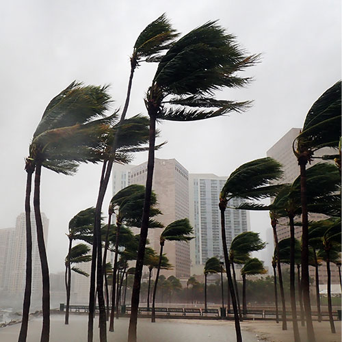

How Often Hurricane Events Occur
Wind speeds associated with hurricanes, typhoons and nor'easters range from 74 mph to more than 157 mph, creating significant risks to buildings, infrastructure and communities. Areas most vulnerable to hurricanes, typhoons and nor'easters include the Atlantic, Pacific and Gulf coasts, Hawaii, U.S. Pacific territories and Caribbean territories.
According to the National Oceanic and Atmospheric Administration (NOAA), since the year 2000, the northern and southern hemispheres have experienced an average of 47 hurricanes and typhoons annually. Of those, the North Atlantic and Caribbean averaged seven hurricanes per year.
Hurricane-Related Losses
Hurricanes and typhoons are among the costliest single weather-related disasters in the U.S.
According to insurer Guardian Service, since 1980 hurricanes have caused over $1.5 trillion USD in damage, averaging $23 billion USD per hurricane across the U.S.
Hurricane Ian in 2022 alone resulted in an estimated $60 – $65 billion USD of insured losses, according to Karen Clark & Company.

Losses Avoided Through Building Codes and Mitigation
Modern building codes and hazard mitigation measures have proven to be some of the most effective tools for reducing hurricane and typhoon damage. By incorporating stronger wind-resistant design requirements, improved roofing and opening protection, enhanced connections between building components and flood-resistant construction practices, communities can significantly reduce property damage, business interruption and recovery costs.
FEMA's Building Codes Save: A Nationwide Study found that adoption of the International Codes® (I-Codes®) could help communities avoid between $132 billion USD and $171 billion USD in cumulative losses through 2040, and $600+ billion USD by 2060.
Using the International Codes (I‑Codes) to Mitigate Hurricane Hazards
The International Codes® (I Codes®), including the 2024 International Building Code® (IBC), International Residential Code® (IRC) and International Existing Building Code® (IBC), provide a comprehensive framework for designing, constructing and retrofitting buildings to better withstand the effects of hurricanes. These codes establish minimum requirements that help protect life and property, reduce wind- and flood-related damage, and support faster community recovery following severe wind and flood events.
The 2024 I-Codes address five broad areas:
- Hazard Identification and Design Criteria: Requirements for addressing hurricane-related hazards, including design wind speeds, flood hazards, storm surge risk, rainfall effects, exposure conditions and building risk categories used to establish design requirements
- Structural Resistance and Load Path Continuity: Provisions that ensure buildings can resist and transfer hurricane forces safely through the structural system, including wind and flood loads acting on foundations, walls, roofs, connections and other structural elements
- Building Envelope and Water Intrusion Protection: Requirements for roofs, exterior walls, openings, glazing, doors and other building components to resist wind pressures, wind-borne debris and wind-driven rain, helping reduce damage from envelope failures and water intrusion
- Flood and Storm Surge Resilience: Provisions for siting, elevation, foundation design, flood-resistant construction and protection of building systems in areas subject to flooding, storm surge and coastal wave action
- Protection of Critical Functions and Occupant Safety: Requirements that enhance life safety during hurricane events, including provisions for emergency egress, protection of critical building systems and where applicable, the design and construction of storm shelters and essential facilities
Key Hurricane Provisions
Click book cover below to reveal/hide code sections.
International Existing Building Code®
Chapter 1 Scope and Administration
Section 104 Duties and Powers of Code Official
- 104.3.1 Determination of substantially improved or substantially damaged existing buildings and structures in flood hazard areas. For applications for reconstruction, rehabilitation, repair, alteration, addition or other improvement of existing buildings or structures located in flood hazard areas, the code official shall determine where the proposed work constitutes substantial improvement or repair of substantial damage. Where the code official determines that the proposed work constitutes substantial improvement or repair of substantial damage, the building is to meet the requirements of Section 1612 of the IBC, or Section R306 of the IRC, as applicable.
Section 106 Construction Documents
- 106.2.4 Exterior wall envelope. Construction documents for work affecting the exterior wall envelope shall describe the exterior wall envelope in sufficient detail to determine compliance with this code. The construction documents shall include manufacturer’s installation instructions that provide supporting documentation regarding maintaining the wind and weather resistance of the exterior wall envelope.
Chapter 2 Definitions
Chapter 2 provides definitions for terms used throughout the IEBC. These definitions provide a common language for designing buildings to resist severe wind events. While the IEBC incorporates the definitions found in the IBC, those terms that are unique to existing buildings can be found within Chapter 2 of the IEBC.
Chapter 4 Repairs
Section 405 Structural
- 405.2.3.1 Evaluation. Damaged buildings are to be evaluated by a registered design professional. The evaluation must establish whether the lateral force-resisting system of the damaged building, if repaired to its predamage state, would comply with the provisions of the IBC for load combinations that include wind effects.
- 405.2.3.3 Extent of repair for noncompliant buildings. If the evaluation does not establish that the lateral force-resisting system of the building in its predamage condition complies with the provisions of Section 405.2.3.1, then the lateral force-resisting system is to be retrofitted.
- 405.2.4.1 Lateral force-resisting elements. Regardless of the level of damage to vertical elements of the lateral force-resisting system, if substantial structural damage to gravity load-carrying components was caused primarily by wind, then the building is to be evaluated and, if noncompliant, it is to be retrofitted. There are a limited number of exceptions.
Chapter 5 Prescriptive Compliance Method
Section 502 Additions
- 502.4 Existing structural elements carrying lateral load. When an addition to an existing building is not structurally independent, the lateral force-resisting system of the existing building and its addition acting together as a single structure shall comply with the IBC. There are a limited number of exceptions.
Section 503 Alterations
- 503.4 Existing structural elements carrying lateral load. When an alteration to an existing building increases the design lateral loads, results in a prohibited structural irregularity as defined in ASCE 7 or decreases the capacity of any existing lateral load-carrying structural element, the lateral force-resisting system is required to meet the requirements of the IBC. There are a limited number of exceptions.
- 503.12 Roof diaphragms resisting wind loads in high-wind regions. When an alteration to an existing building requires a permit for reroofing and involves removal of roofing materials from more than 50% of the roof diaphragm in areas where the basic wind speed is greater than 130 mph, the roof diaphragms and its connections are to be evaluated for the wind loads specified in the IBC. When diaphragms and connections are not capable of resisting 75% of those wind loads, they are to be replaced or strengthened.
Section 506 Change of Occupancy
- 506.5.2 Snow and wind loads. Where a change of occupancy results in a building being assigned to a higher risk category, the building is required to satisfy the requirements of the IBC for the new risk category unless the area of the new occupancy is less than 10% of the building area.
Chapter 7 Alterations — Level 1
Section 706 Structural
- 706.3.2 Roof diaphragms resisting wind loads in high-wind regions. When reroofing involves removal of roofing materials from more than 50% of the roof diaphragm in areas where the basic wind speed is greater than 130 mph, the roof diaphragms and its connections are to be evaluated for the wind loads specified in the IBC. When diaphragms and connections are not capable of resisting 75% of those wind loads, they are to be replaced or strengthened.
Chapter 8 Alterations — Level 2
Section 805 Structural
- 805.3 Existing structural elements resisting lateral loads. When an alteration to an existing building increases the design lateral loads, results in a prohibited structural irregularity as defined in ASCE 7 or decreases the capacity of any existing lateral load-carrying structural element, the lateral force-resisting system is required to meet the requirements of the IBC. There are a limited number of exceptions.
Chapter 10 Change of Occupancy
Section 1006 Structural
- 1006.2 Snow and wind loads.
Where a change of occupancy results in a structure being assigned to a higher risk category, the structure is required to satisfy the requirements of the IBC for the new risk category unless the area of the new occupancy is less than 10% of the building area.
Chapter 11 Additions
Section 1103 Structural
- 1103.2 Lateral force-resisting system. When an addition to an existing building is not structurally independent, the lateral force-resisting system of the existing building and its addition acting together as a single structure shall comply with the IBC. There are a limited number of exceptions. When calculating demand-capacity ratios for wind, the code wind forces in effect at the time are to be utilized.
Chapter 14 Relocated or Moved Buildings
Section 1402 Requirements
- 1402.3 Wind loads. Relocated buildings are required to comply with IBC or IRC wind provisions, as applicable with only a few exceptions.
Chapter 15 Construction Safeguards
Section 1504 Protection of Pedestrians
- 1504.1.7 Adjacent to excavations. Barriers are to be capable of resisting wind pressure as specified in the IBC.
Appendix C Guidelines for the Wind Retrofit of Existing Buildings
Appendix C is intended to provide prescriptive methods for structural retrofitting of existing buildings to increase their resistance to wind loads. It is intended for voluntary use where the basic wind speed, V, is greater than 130 mph. The provisions of this chapter do not necessarily satisfy requirements for new construction.
International Residential Code®
Chapter 2 Definitions
Chapter 2 provides definitions for terms used throughout the IRC. These definitions provide a common language for designing buildings to resist severe wind events. They help us understand wind hazard intensity, determine the forces buildings must withstand, and describe the structural systems and connections needed to create a continuous load path. Together, they ensure that buildings are designed with appropriate safety factors, sturdier connections and stronger performance in high-risk areas.
Chapter 3 Building Planning
Chapter 3 contains a wide array of building planning requirements that are critical to designing a safe and usable building. This includes but is not limited to general structural design as it relates to wind. Examples of wind-related provisions include:
Section R301 Design Criteria
- R301.2.1 Wind design criteria Buildings and portions thereof shall be constructed in accordance with the wind provisions of the IRC using the ultimate design wind speeds provided. Additionally, where not otherwise specified, the wind loads provided are to be adjusted for height and exposure and are to be used to determine design load performance requirements for wall coverings, curtain walls, roof coverings, exterior windows, skylights, garage doors and exterior doors. The IRC also requires that a continuous load path be provided to transmit the applicable uplift forces from the roof assembly to the foundation.
- R301.2.1.1 Wind limitations and wind design required The wind provisions of the IRC do not apply to the design of buildings where the ultimate design wind speed equals or exceeds 140 mph There are a limited number of exceptions.
- R301.2.1.1.1 Sunrooms Sunrooms are required to comply with AAMA/NPEA/NSA 2100.
- R301.2.1.2 Protection of openings Exterior glazing in buildings located in windborne debris regions are required to be protected from windborne debris. This is accomplished by requiring that glazed opening be protected from windborne debris by meeting the requirements of the Large Missile Test of ASTM E1886 and ASTM E1996. Garage door glazed opening protection for windborne debris is required to be of an approved impact-resisting standard or ANSI/DASMA 115. The only exception to this is if wood structural panels are employed. A fastening schedule for wood structural panels is provided in table format.
- R301.2.1.3 Wind speed conversion The IRC provides a method of converting from nominal design wind speeds to ultimate design wind speeds in Table R301.2.1.3.
- R301.2.1.4 Exposure category The IRC requires that buildings be designed by considering each direction the wind approaches from and its corresponding exposure category adequately reflecting the characteristics of ground surface irregularities. The IRC also requires that account be taken of variations in ground surface roughness that arise from natural topography and vegetation as well as from constructed features. For any given wind direction, the exposure in which a specific building or other structure is sited shall be assessed as being one of the following categories: Exposure B (Urban and suburban areas), Exposure C (Open terrain with scattered obstructions) or Exposure D (Flat, unobstructed areas).
- R301.2.1.5 Topographic wind effects The IRC requires that areas having local historical data documenting structural damage to buildings caused by wind speed-up at isolated hills, ridges and escarpments are to be considered in the design of the building. In these designated areas, topographic wind effects shall apply only to buildings sited on the top half of an isolated hill, ridge or escarpment where the average slope of the top half of the hill, ridge or escarpment is 10% or greater and the hill, ridge or escarpment is 60 feet or greater in height for Exposure B, 30 feet or greater in height for Exposure C, and 15 feet or greater in height for Exposure D.
- R301.2.2.7 Height limitations The IRC sets limitations on wood-framed buildings to three stories above grade plane. Cold-formed steel-framed buildings are limited to less than or equal to three stories above grade plane. Structural insulated panel buildings are limited to two stories above grade plane.
Section R307 Storm Shelters
- R307.1 General This section applies to the design, construction and installation of storm shelters where constructed as either separate detached buildings or rooms or spaces within buildings for the purpose of providing protection from hurricanes and other severe windstorms.
Section R329 Solar Energy Systems
- R329.4.1.2 Wind load Rooftop-mounted photovoltaic panel or module systems and their supports are to be designed and installed to resist specified component and cladding loads.
Chapter 4 Foundations
Chapter 4 provides requirements for constructing footings and walls for foundations of wood, masonry, concrete and precast concrete. Namely a foundation’s ability to support the required design loads including the effects from wind loads. Examples of wind-related provisions include:
Section R404 Foundation and Retaining Walls
- R404.5.2 Precast concrete foundation design drawings The IRC requires that precast concrete foundation wall design drawings shall be submitted to the building official and approved prior to installation. These drawings are to include, at a minimum, the following information:
- Design loading as applicable.
- Footing design and material.
- Concentrated loads and their points of application.
- Soil bearing capacity.
- Maximum allowable total uniform load.
- Seismic design category.
- Basic wind speed.
Chapter 5 Floors
Chapter 5 provides the requirements for the design and construction of floor systems that will be capable of supporting minimum required design loads. Namely a floor’s ability to support the required design loads including the effects from wind loads. This chapter covers wood floor framing, wood floors on the ground and cold-formed steel floor framing. Examples of wind-related provisions include:
Section R502 Wood Floor Framing
- R502.12.4 Truss design drawings The IRC requires that truss design drawings are to be submitted to the building official and approved prior to installation. It also requires that the truss design drawings be provided with the shipment of trusses delivered to the job site and include, at a minimum, the following information:
- Slope or depth, span and spacing.
- Location of all joints.
- Required bearing widths.
- Design loads as applicable:
- 4.1. Top chord live load.
4.2. Top chord dead load.
4.3. Bottom chord live load.
4.4. Bottom chord dead load.
4.5. Concentrated loads and their points of application.
4.6. Controlling wind and earthquake loads.
- 4.1. Top chord live load.
Section R505 Cold-Formed Steel Floor Framing
- R505.1.1 Applicability limits The IRC provides provisions that control the construction of cold-formed steel floor framing for buildings and limits them to not greater than 60 feet in length perpendicular to the joist span, not greater than 40 feet in width parallel to the joist span and less than or equal to three stories above grade plane. Additionally, cold-formed steel floor framing is limited to sites where the ultimate design wind speed is less than 140 mph Exposure Category B or C.
- TABLE R505.3.1(1) The IRC also provides floor-to-foundation or bearing wall connection requirements in tabular form in TABLE R505.3.1(1).
Chapter 6 Wall Construction
Chapter 6 contains prescriptive provisions for the design and construction of walls. Namely a wall’s ability to support the required design loads including the effects from wind loads. The wall construction covered in Chapter 6 consists of five different types: wood framed, cold-formed steel framed, masonry, concrete and structural insulated panel (SIP). This chapter covers wood floor framing, wood floors on the ground and cold-formed steel floor framing. Examples of wind-related provisions include:
Section R602 Wood Wall Framing
- R602.3 Design and construction The IRC requires exterior walls of wood-frame construction to be designed and constructed in accordance with the prescriptive provisions of this chapter or in accordance with AWC NDS. It also requires that components of exterior walls and wall sheathing are to be fastened directly to framing members and, where placed on the exterior side of an exterior wall, to be capable of resisting the wind pressures.
These prescriptive requirements are listed in tabular format in TABLE R602.3(3) titled Requirements for Wood Structural Panel Wall Sheathing Used to Resist Wind Pressures.
- R602.3.5 Braced wall panel uplift load path The IRC requires that exterior wall panels that support roof rafters or trusses (including stories below top story) to have the framing members connected to resist gravity and wind uplift loads. These prescriptive requirements are listed in tabular format in the following tables:
- TABLE R602.10.3(1) BRACING REQUIREMENTS BASED ON WIND SPEED
- TABLE R602.10.6.4 TENSION STRAP CAPACITY FOR RESISTING WIND PRESSURES PERPENDICULAR TO METHODS PFH, PFG AND CS-PF BRACED WALL PANELS
Section R603 Cold-Formed Steel Wall Framing
The IRC provides prescriptive requirements regarding the use of cold-formed steel wall framing. The specific provisions can be found in the following tables:
- TABLE R603.3.1 WALL TO FOUNDATION OR FLOOR CONNECTION REQUIREMENTS
- TABLE R603.3.1.1(1) GABLE ENDWALL TO FLOOR CONNECTION REQUIREMENTS
- TABLE R603.3.2(1 - 16) 40-FOOT-WIDE BUILDING SUPPORTING TWO FLOORS, ROOF AND CEILING
- TABLE R603.3.2.1(1 - 2) ALL BUILDING WIDTHS GABLE ENDWALLS OVER 10 FEET IN HEIGHT
- TABLE R603.7(1 - 2) HEADER TO KING STUD CONNECTION REQUIREMENTS
- TABLE R603.8 HEAD AND SILL TRACK SPAN
- R603.9.4.1 Ultimate design wind speeds greater than 130 mph. The IRC also sets out additional limitations on these walls by specifying that when the ultimate design wind speeds exceed 130 mph for Exposure Category C, the walls are to be provided with direct uplift connections.
Section R606 General Masonry Construction
- R606.4.4 Parapet walls The IRC provides prescriptive requirements on unreinforced solid masonry parapet walls that are not less than 8 inches thick, and their height is not to exceed four times their thickness. Similarly, unreinforced hollow unit masonry parapet walls are to be not less than 8 inches thick, and their height shall not exceed three times their thickness.
Section R607 Glass Unit Masonry
- R607.4.1 Exterior standard-unit panels The IRC establishes a maximum area of each individual standard-unit glass masonry panel of 144 square feet where the design wind pressure is 20 pounds per square. It also sets the maximum panel dimension between structural supports at 25 feet in width or 20 feet in height.
Section R608 Exterior Concrete Wall Construction
- R608.2 Applicability limits The prescriptive provisions of this section apply to the construction of exterior concrete walls for buildings not greater than 60 feet in plan dimensions, floors with clear spans not greater than 32 feet and roofs with clear spans not greater than 40 feet and Buildings not exceeding 35 feet in mean roof height or two stories in height above grade. Additionally, walls constructed in accordance with the provisions of this section are limited to a maximum design wind speed of 160 mph Exposure B, 136 mph Exposure C and 125 mph Exposure D.
- R608.6.2 Wall reinforcement for wind The prescriptive requirements of this section state that vertical wall reinforcement for resistance to out-of-plane wind forces is to be determined using Tables R608.6(1), R608.6(2), R608.6(3) or R608.6(4). For the design of nonload-bearing walls, Tables R608.6(1), R608.6(2) and R608.6(3) are to be used.
Additionally, there are to be a vertical bars at corners of exterior walls with a minimum horizontal reinforcement of four No. 4 bars [Grade 40 (280 MPa)] placed as follows: top bar within 12 inches (305 mm) of the top of the wall, bottom bar within 12 inches (305 mm) of the finish floor and one bar each at approximately one-third and two-thirds of the wall height.
Section R609 Exterior Windows and Doors
- R609.2 Performance The IRC requires that exterior windows and doors are to be capable of resisting design wind loads adjusted for height and exposure.
- R609.4.1 Garage door labeling Garage doors are to be labeled with a permanent label provided by the garage door manufacturer that identifies the garage door manufacturer, the garage door model/series number, the positive and negative design wind pressure rating, the installation instruction drawing reference number and the applicable test standard.
- R609.6 Windborne debris protection. The IRC requires that all exterior windows, glass doors and doors with glass in buildings located in windborne debris regions are to be protected against windborne debris.
Chapter 7 Wall Covering
Chapter 7 establishes the various types of materials, materials standards and methods of application permitted as interior and exterior wall coverings. Exterior wall coverings regulated by this section include aluminum, stone and masonry veneer, wood, hardboard, particleboard, wood structural panel siding, wood shakes and shingles, exterior plaster, steel, vinyl, fiber cement and exterior insulation finish systems. This chapter also contains requirements relating to wind resistance for exterior wall coverings. Examples of wind-related provisions include:
Section R703 Exterior wall Covering
- R703.1.2 Wind resistance The IRC requires that exterior wall coverings, siding, exterior soffit and backing materials and their attachments are to be capable of resisting wind loads.
- R703.3.2 Wind limitations Among the limitations for the IRC’s prescriptive requirements, when the design wind pressure exceeds 30 psf, the attachment of wall coverings is to be designed to resist component and cladding loads for walls and adjusted for height and exposure. The prescriptive attachment requirements are tabularized into TABLE R703.11.2 title Required Minimum Wind Load Design Pressure Rating for Vinyl Siding Installed Over Foam Plastic Sheathing Alone.
Section R703 Exterior wall Covering
- R704.1 General wind limitations Among the IRC’s limitations, when the design wind pressure exceeds 30 psf, the attachment of exterior soffits is to comply with the design wind pressure determined using the component and cladding loads for walls using an effective wind area of 10 square feet and adjusted for height and exposure.
- R704.3.1 Vinyl exterior soffit panels When the exterior soffit panels are vinyl, their attachments are to be capable of resisting wind loads for walls using an effective wind area of 10 square feet and adjusted for height and exposure and installed using fasteners specified by the manufacturer. They are also to be fastened at both ends to a supporting component such as a nailing strip, fascia or subfascia component. Where the unsupported span of exterior soffit panels is greater than 12 inches, intermediate nailing strips are to be provided.
- R704.3.2 Fiber-cement exterior soffit panels. When the exterior soffit panels are Fiber-cement, their attachments are to be capable of resisting wind loads for walls using an effective wind area of 10 square feet and adjusted for height and exposure and installed using fasteners specified by the manufacturer.
- R704.3.3 Hardboard exterior soffit panels. When the exterior soffit panels are Hardboard, their attachments are to be capable of resisting wind loads for walls using an effective wind area of 10 square feet and adjusted for height and exposure and installed using fasteners specified by the manufacturer.
- R704.3.4 Wood structural panel exterior soffit. When the exterior soffit panels are structural wood, their attachments are to be capable of resisting wind loads for walls using an effective wind area of 10 square feet and adjusted for height and exposure and installed using fasteners specified by the manufacturer.
Chapter 8 Roof-Ceiling Construction
Chapter 8 addresses the design and construction of roof-ceiling systems. This chapter contains two roof-ceiling framing systems: wood framing and cold-formed steel framing. This chapter also contains requirements relating to wind resistance for these systems. Examples of wind-related provisions include:
Section R802 Wood Roof Framing
- R802.10.1 Truss design drawings. The IRC requires that truss design drawings are to be submitted to the building official and approved prior to installation. It also requires that the truss design drawings be provided with the shipment of trusses delivered to the job site and include, at a minimum, the following information:
- Slope or depth, span and spacing.
- Location of all joints.
- Required bearing widths.
- Design loads as applicable:
- 4.1. Top chord live load.
4.2. Top chord dead load.
4.3. Bottom chord live load.
4.4. Bottom chord dead load.
4.5. Concentrated loads and their points of application.
- 4.1. Top chord live load.
- R802.10.2.1 Applicability limits The IRC provides provisions that control the construction of wood roof framing for buildings and limits them to not greater than 60 feet in length perpendicular to the joist span, not greater than 36 feet in width parallel to the joist span and less than or equal to three stories above grade plane. Additionally, wood roof framing is limited to sites where the ultimate design wind speed is less than 140 mph Exposure Category B or C.
- R802.11 Roof tie uplift resistance The IRC requires that roof assemblies be provided with uplift resistance based on the design wind loads. Exceptions include rafters or trusses that are attached to their supporting wall assemblies where the uplift force per rafter or truss does not exceed 200 pounds or where the basic wind speed does not exceed 115 mph for exposure category B and the roof pitch is 5 units vertical in 12 units horizontal or greater. The values for rafter or truss uplift connection forces from wind can be found in TABLE R802.11.
- R802.11.1 Truss uplift resistance The IRC requires that roof trusses be attached to supporting wall assemblies by connections capable of resisting uplift forces as specified on the truss design drawings for the ultimate design wind speed.
Section R804 Cold-Formed Steel Roof Framing
- R804.1.1 Applicability limits. The IRC provides provisions that control the construction of cold-formed steel roof framing for buildings and limits them to not greater than 60 feet in length perpendicular to the joist span, not greater than 40 feet in width parallel to the joist span and less than or equal to three stories above grade plane. Additionally, cold-formed steel roof framing is limited to sites where the ultimate design wind speed is less than 140 mph for Exposure Category B or C. Roof framing fastening schedules can be found in TABLE R804.3.
Chapter 9 Roof Assemblies
Chapter 9 addresses the design and construction of roof assemblies. A roof assembly includes the roof deck, substrate or thermal barrier, insulation, vapor retarder and roof covering. Among other requirements, this chapter identifies the requirement for wind resistance of roof coverings. The types of roof covering materials and installation addressed by Chapter 9 are: asphalt shingles, clay and concrete tile, metal roof shingles, mineral-surfaced roll roofing, slate and slate-type shingles, wood shakes and shingles, built-up roofs, metal roof panels, modified bitumen roofing, thermoset and thermoplastic single-ply roofing, sprayed polyurethane foam roofing, liquid applied coatings and building-integrated photovoltaic (BIPV) roof coverings. Examples of wind-related provisions include:
Section R905 Requirements for Roof Coverings
The IRC specifies requirements for roof underpayments in the following tables:
- TABLE R905.1.1(1) UNDERLAYMENT TYPES
- TABLE R905.1.1(2) UNDERLAYMENT APPLICATION
- TABLE R905.1.1(3) UNDERLAYMENT ATTACHMENT
- R905.2.4.1 Wind resistance of asphalt shingles. The IRC requires that asphalt shingles shall be tested in accordance with ASTM D7158and that they meet specific classification requirements relating to the appropriate ultimate design wind speed. The IRC also requires that asphalt shingle packaging bears a label to indicate compliance with ASTM D7158.
- R905.3.6 Wind resistance of concrete and clay tile. In regions where wind design is required the IRC requires that wind loads on concrete and clay tile are to be determined.
- R905.4.4.1 Wind resistance of metal roof shingles. The IRC requires that metal roof shingles fastened to wood structural panels, solid lumber sheathing or closely fitted lumber sheathing are to be tested in accordance with ASTM D3161, FM 4474, UL 580 or UL 1897 for the appropriate maximum basic wind speed. Additionally, metal shingle packaging is to bear a label indicating compliance with ASTM D3161.
- R905.5.6 Wind resistance of mineral-surfaced roll roofing. The IRC requires that mineral-surfaced roll roofing shall be installed to resist the component and cladding wind loads adjusted for height and exposure.
- R905.6.5 Wind resistance of slate shingles. The IRC requires that slate shingles are to be tested in accordance with ASTM D3161 and its packaging is to bear a label indicating compliance with ASTM D3161.
- R905.7.5 Wind resistance of wood shingles. In regions where wind design is required the IRC requires that wood shingles are to be installed to resist the component and cladding wind loads and adjusted for height and exposure.
- R905.8.6 Wind resistance of wood shakes. In regions where wind design is required the IRC requires that wood shakes are to be installed to resist the component and cladding wind loads and adjusted for height and exposure.
- R905.9.4 Wind resistance of built-up roofs. In regions where wind design is required the IRC requires that Built-up roof coverings are to be installed to resist the component and cladding wind loads and adjusted for height and exposure.
- R905.10.5 Wind resistance of metal roof panels. In regions where wind design is required the IRC requires that metal roof panels are to be installed to resist the component and cladding wind loads and adjusted for height and exposure. In cases where metal roof panels are applied to a solid or closely fitted deck they are to be tested for wind resistance as appropriate and with a limited number of exceptions.
- R905.11.4 Wind resistance of modified bitumen roofing. In regions where wind design is required the IRC requires that Modified bitumen roofing is to be installed to resist the component and cladding wind loads and adjusted for height and exposure.
- R905.12.4 Wind resistance of single-ply roofing.
In regions where wind design is required the IRC requires that Single-ply roofing is to be installed to resist the component and cladding wind loads and adjusted for height and exposure. - R905.13.4 Wind resistance of sprayed polyurethane foam roofing. In regions where wind design is required the IRC requires that Sprayed polyurethane foam roofing is to be installed to resist the component and cladding wind loads and adjusted for height and exposure.
- R905.14.4 Wind resistance of liquid-applied roofing. In regions where wind design is required the IRC requires that Liquid-applied roofing is to be installed to resist the component and cladding wind loads and adjusted for height and exposure.
International Building Code®
Chapter 2 Definitions
Chapter 2 provides definitions for terms used throughout the IBC. These definitions provide a common language for designing buildings to resist severe wind events. They help us understand wind hazard intensity, determine the forces buildings must withstand and describe the structural systems and connections needed to create a continuous load path. Together, they ensure that buildings are designed with appropriate safety factors, sturdier connections and stronger performance in high-risk areas.
Chapter 4 Special Detailed Requirements Based on Occupancy and Use
Section 423 Storm Shelters: This entire section applies to the design and construction of storm shelters constructed as separate detached buildings or constructed as rooms or spaces within buildings for the purpose of providing protection from tornadoes, hurricanes and other severe windstorms during the storm. This section specifies where storm shelters are required and provides requirements for the design and construction of storm shelters.
- 423.2 Construction – storm shelters are to be constructed in accordance with this code and ICC 500 and shall be designated as hurricane shelters, tornado shelters or combined hurricane and tornado shelters.
- 423.3 Occupancy classification – occupancy classifications for storm shelters are determined based on whether the shelter is a dedicated storm shelter, a storm shelter within a host building, its design occupancy load and its location relative the building(s) it services.
Chapter 9 Fire Protection and Life Safety Systems
Section 909 Smoke Control Systems
- 909.4.1 Smoke control – stack effect. Smoke control system is designed so normal or reverse stack effect doesn't interfere is the system's capabilities.
- 909.4.3 Smoke control – wind effect. Smoke control system design considers adverse wind effects.
- 909.20.4 Smoke control - stairway and ramp pressurization. Pressurization relative to stairway and ramp
Section 913 Fire Pumps
- 913.2 Fire pumps – interruption of service. Protection of fire pump, driver and controller against service interruption through damage caused by windstorm, flood and other special weather and environmental conditions.
Chapter 10 Means of Egress
Section 1031 Emergency Escape and Rescue
- 1031.2 Where required – storm shelter exception. Storm shelters are excepted to include emergency escape and rescue openings.
Chapter 11 Accessibility
Section 1112 Signage
- 1112.5.2 Variable message signs – emergency shelters. Emergency shelters must provide variable message signage conveying emergency-related information.
Chapter 14 Exterior Walls
Section 1402 Performance Requirements
- 1402.3 Performance requirements - wind resistance. Exterior walls and coverings, soffits and associated openings designed to resist superimposed loads.
Section 1404 Installation of Wall Coverings
- 1404.12.1 Attachment. Exterior metal veneer attachment fastenings and their spacing designed to resist wind loads specified in Section 1609.
- 1404.15 Vinyl siding and insulated vinyl siding - design wind pressure requirements. Vinyl siding permitted on exterior walls where the design wind pressure does not exceed 30 psf., or else compliance with Chapter 16.
- 1404.15.2 Installation over foam plastic insulated sheathing - design pressure requirements. Vinyl siding over foam plastic sheathing to comply with Section 1404.15 and have wind load design pressure rating in accordance with Table 1404.15.2.
- 1404.17 Fiber cement siding. Fiber-cement siding permitted on exterior walls for wind pressure resistance or basic wind speed exposures as indicated by the manufacturer's listing and installation instructions.
- 1404.18 Polypropylene siding. Polypropylene siding is limited to exterior walls in areas meeting maximum basic wind speeds specified in Chapter 16, with building height considerations.
Section 1406 Metal Composite Material (MCM)
- 1406.4 Structural design. Metal composite materials designed and constructed to resist wind loads as required by Chapter 16 for components and cladding.
- 1406.5 Approval. Results of approved tests or engineering analysis to be submitted to the building official for compliance verification with Chapter 16 for wind loads.
- 1406.6 Weather resistance. MCM systems must be designed and constructed to resist wind and rain in accordance with this section and manufacturer's installation instructions.
Section 1407 Exterior Insulation and Finish Systems (EIFS)
- 1407.3 Structural design. Underlying structural framing and substrate to be designed and constructed to resist loads as required by Chapter 16.
- 1407.4 Weather resistance. System designed and constructed to resist wind and rain in accordance with this section and manufacturer's application instructions.
Section 1408 High-Pressure Decorative Exterior-Grade Compact Laminates (HPL)
- 11408.4 Structural design. HPL system to be designed and constructed to resist wind loads as required by Chapter 16 for components and cladding.
- 1408.5 Approval. Results of approved tests or engineering analysis to be submitted to the building official for compliance verification with Chapter 16 for wind loads.
- 1408.6 Weather resistance. HPL systems must be designed and constructed to resist wind and rain in accordance with this section and manufacturer's installation instructions.
Section 1409 Insulated Metal Panel (IMP)
- 1409.2 Structural design. Structural design of IMP system to be in accordance with this section.
- 1409.3 Weather resistance. IMP systems must be designed and constructed to resist wind and rain in accordance with this section and manufacturer's installation instructions
Section 1412 Soffits and Fascias at Roof Overhangs
- 1412.2 General wind requirements. Soffits and fascias capable of resisting components and cladding loads for walls in accordance with Chapter 16 using an effective wind area of 10 square feet.
- 1412.3 Vinyl & aluminum soffit panels. Vinyl and aluminum soffit panels to meet fastener and installation instruction requirements based on required design wind pressures.
- 1412.5 Hardboard soffit panels. Hardboard soffit panel minimum thickness and installation instruction requirements to meet required design wind pressures.
- 1412.7 Aluminum fascia. Aluminum fascia to meet minimum thickness and manufacturer's installation instruction requirements.
Chapter 15 Roof Assemblies and Rooftop Structures
Section 1504 Performance Requirements
- 1504.1 Wind resistance of roofs. Roof decks and roof coverings to be designed in accordance with Section 1504.
- 1504.2 Wind resistance of asphalt shingles. Asphalt shingles tested to ASTM D7158 and meet classification requirements of Table 1504.2 for maximum basic wind speed.
- 1504.3 Wind resistance of clay and concrete tile. Wind loads on clay and concrete tile roof coverings to be in accordance with Section 1609.6.
- 1504.4 Wind resistance of nonballasted roofs (includes built-up, modified bitumen, fully adhered/mechanically attached, metal shingles, metal panels, and slate). Roof coverings mechanically attached to the roof deck to be designed to resist design wind load pressures with Section 1609.6.2.
- 1504.5 Ballasted low-slope single-ply roof systems. Ballasted low-slope single-ply roof system coverings to be installed in accordance with Section 1507.12 and designed to ANSI/SPRI RP-4.
- 1504.6 Edge systems for low-slope roofs. Metal edge systems installed on specific low-slope roof systems to be designed and installed for wind loads to Chapter 16 and certain test standards.
- 1504.8 Wind resistance of aggregate-surfaced roofs – parapets. Parapets provided for aggregate surfaced roofs and comply with Table 1504.8 and include installation location requirements.
Section 1507 Requirements for Roof Coverings
- 1507.1.1 Underlayment. Underlayment requirements based on roof covering materials through this section and 3 associated Table 1507.1.1 tables.
- 1507.3.7 Clay and concrete tile attachment. Clay and concrete roof tiles to be fastened in accordance with Table 1507.3.7.
- 1507.16.8 Building Integrated Photo Voltaic (BIPV) shingles - wind resistance. Shingles to comply with requirements of Table 1504.2 for the appropriate maximum basic wind speed.
- 1507.17.4 Building Integrated Photo Voltaic (BIPV) panels – underlayment. Addresses underlayment application method and 1507.4.1 further addresses high-wind attachment requirements.
Chapter 16 Structural Design
Section 1602 Notations
- 1602.1 Notations (abbreviations). Chapter notations defined.
Section 1603 Construction Documents
- 1603.1.4 Wind design data. Construction documents for wind design data.
Section 1604 General Design Requirements
- 1604.3 Serviceability . General design requirements for structural systems and members.
- 1604.5 Risk category. Building risk category is established based on Table 1604.5
- 1604.8 Anchorage. Buildings must have anchorage in accordance with Sections 1608.1 through 1604.8.3.
- 1604.9 Wind and seismic detailing. Lateral force-resisting systems to meet seismic detailing requirements where wind load effects are greater than seismic load effects.
- 1604.10. Loads on storm shelters. Loads and load combinations on storm shelters to be determined in accordance with ICC 500.
Section 1605 Load Combinations: Requirements in this section address a building's strength load combinations.
Section 1609 Wind Loads: Requirements in this section address a building's minimum wind load designs.
Section 1612 Flood Loads
- 1612.4 Flood hazard documentation. Outlines design documentation criteria for construction in coastal high hazard and coastal A zones.
Chapter 17 Special Inspections and Tests
Section 1704 Special Inspections and Tests, Contractor Responsibility and Structural Observation
- 1704.3.3 Statement of special inspections – wind requirements. Statement identifying the designated seismic and seismic force-resisting systems subject to special inspections or tests.
Section 1705 Required Special Inspections and Tests
- 1705.12 Special inspections for wind resistance. Required wind exposure categories where special inspections for wind resistance is required.
Section 1709 Preconstruction Load Tests
- 1709.5 . Exterior window and door assemblies – wind pressure requirements. Pre-construction load tests - design pressure rating requirements for exterior windows and doors.
Chapter 18 Soils and Foundations
Section 1806 Presumptive Load-Bearing Values of Soils
- 1806.1 Presumptive load-bearing values of soils - load combinations. Requirements for load-bearing values used with the allowable stress design load combinations
Section 1810 Deep Foundations
- 1810.3.2.6 Design and detailing – materials – allowable stresses. Maximum allowable stresses for materials used in deep foundations as listed in Table 1810.3.2.6.
- 1810.3.3.1.5 Design and detailing – determination of allowable loads – allowable axial load – uplift capacity of single deep foundation element. Uplift capacity of a single deep foundation element to be determined by an approved method of analysis
Chapter 21 Masonry
Section 2109 Empirical Design of Adobe Masonry
- 2109.1.1 Empirical design of Adobe masonry – limitations. Adobe masonry design limitations based on specified Sections in this code, TMS 402-16 modification for wind
Chapter 23 Wood
Section 2304 General Construction Requirements
- 2304.6 Exterior wall sheathing. Wood products used as exterior wall sheathing and their connections must be designed and installed according to the maximum basic wind speed and wind pressures in this section.
Section 2305 General Design Requirements for Lateral Force-Resisting Systems: Lateral force-resisting systems using wood products in shear walls and diaphragms must meet the design requirements of this section.
Section 2306 Allowable Stress Design: This section addresses allowable stress designs for a variety of wood products and applications.
Section 2307 Load and Resistance Factor Design: When using load and resistance factor design, wood elements and structures must meet the requirements of ANSI/AWC NDS and AWC SDPWS.
Section 2308 Conventional Light-Frame Construction
- 2308.2 Limitations. Buildings of light-frame construction must be designed and constructed in accordance with the wind and load requirements of this section which include provisions for tornado loads and hurricane-prone regions.
- 2308.11.4 Roof and ceiling framing. Roof construction must be attached to the wall below with connections capable of resisting the required uplift loads according to the table or the truss design drawings.
Chapter 24 Glass and Glazing
Section 2404 Wind, Snow, Seismic and Dead Loads on Glass
- 2404.1 Vertical glass. Vertical glass (sloped 15 degrees or less from vertical) in exterior applications must be designed to resist wind loads in accordance with the requirements in section 1609.
- 2404.2 Sloped glass. Glass sloped more than 15 degrees from vertical in exterior applications must be designed to resist the most critical load combination determined by the equations in this section.
- 2404.3 Wired, patterned, and sandblasted glass (vertical and sloped). Wired, patterned and sandblasted glass, both vertical and sloped, in exterior applications must be designed to resist wind loads according to section 1609 and the equations in this section.
Chapter 25 Gypsum Panel Products and Plaster
Section 2505 Shear Wall Construction: Gypsum panel products and plasters used in shear wall assemblies must comply with this section.
Section 2508 Gypsum Construction
- 2508.6 Horizontal gypsum panel product diaphragm ceilings. Gypsum panel products used in horizontal diaphragm ceilings must meet the requirements of this section.
Chapter 26 Plastic
Section 2603 Foam Plastic Insulation
- 2603.10 Wind resistance. Foam plastic insulation used as sheathing must comply with wind resistance required by ANSI/SBCA FS 100.
Chapter 30 Elevators and Conveying Systems
Section 3001 General
- 3001.6 Structural design. Elevators, escalators and other conveying systems must be designed according to the applicable wind load requirements of section 1609.
Chapter 31 Special Construction
Section 3102 Membrane Structures
- 3102.7 Engineering design. Membrane structures must be designed to sustain a variety of loads, including the wind loads specified in Chapter 16.
Section 3103 Temporary Structures
- 3103.6.1.2 Structural requirements – structural loads – wind loads. Design wind loads for public-occupancy temporary structures, like tents and bleachers, may be reduced by the factors listed in this section and the accompanying table.
- 3103.8 Controlled occupancy procedures. Where controlled occupancy procedures are required for a public-occupancy temporary structure, wind speeds must be monitored before and during occupancy, and the structure must be vacated if the design wind speed is expected to be exceeded.
Section 3105 Awnings and Canopies
- 3105.2 Design and construction. Awnings and canopies must be designed to handle wind loads as required in Chapter 16.
Section 3111 Solar Energy Systems
- 3111.1.1 General - wind resistance. Roof-mounted photovoltaic systems and solar thermal collectors must be designed according to section 1609.
Section 3113 Relocatable Buildings
- 3113.2 Supplemental information. Information submitted to the AHJ for relocatable buildings must include the design loads specified in this section.
- 3113.3 Manufacturer's data plate. The manufacturer's data plate on relocatable buildings must include the design loads specified in this section.
Section 3114 Intermodal Shipping Containers
- 3114.8 Structural. Intermodal shipping containers that conform to ISO 1496-1 to be used as buildings or structures must be designed to meet Chapter 16 and this section.
Chapter 33 Safeguards During Construction
Section 3306
- 3306.9 Adjacent to excavations. Barriers adjacent to excavation sites must be designed to resist wind pressures specified in Chapter 16.
Hurricane Resources
Preparedness
Emergency Planning
Visit Ready.gov for emergency planning, evacuation preparation, alerts and household readiness resources for hurricanes.
Training for Officials
When Disaster Strikes Institute’s Disaster Planning for the Building Department course outlines roles, responsibilities and readiness strategies before hurricane-related disasters.
Response
Stay Safe
Learn how to stay safe during and after a wind event. Follow evacuation orders, avoid debris and flooded areas and stay informed through local emergency alerts.
Training for Officials
When Disaster Strikes Institute’s Evaluator and Coordinator Training courses teach professionals how to safely assess post event structures and determine habitability.
Recovery
Damage Assessment
Damage assessments help determine structural integrity, identify hazardous conditions and guide decisions about repair, demolition or rebuilding. Updated 2024 I Codes include clarified definitions and documentation requirements to support efficient recovery and consistent enforcement.
Pairing Mitigation with Local Recovery
When communities begin recovering after a severe hurricane event, it’s essential to rebuild with future resilience in mind. Local governmental leaders, recovery committees and planning groups can integrate mitigation into every recovery decision by using established assessment methods, such as state and local hazard mitigation plans and applying a multi-hazard approach to rebuilding.
Use hazard mitigation plans as roadmaps
Reference state or local hazard mitigation plans to guide decisions on where and how recovery projects should be designed, funded and implemented.
Conduct post‑event damage & risk assessments
Evaluate the extent of damage, identify recurring problem areas and document vulnerabilities to inform mitigation‑focused rebuilding.
Embed mitigation in all recovery discussions
Ensure that community town hall meetings, planning meetings and community workshops include mitigation options as part of every proposed solution.
Prioritize multi‑hazard strategies
Consider community hazards and risks beyond hurricane events (e.g. flooding, wildfire, earthquakes, etc.) and pursue solutions that reduce exposure to multiple hazards at once.
Leverage recovery funding for mitigation
Explore opportunities within federal, state and local disaster assistance funding programs that allow or encourage mitigation as part of repair and reconstruction.
Rebuild with resilience
Encourage use of hurricane-resistant materials and installation methods and infrastructure designs that address long‑term risk.
Engage the community
Involve residents, businesses and local organizations to ensure mitigation measures reflect community needs and support long‑term resilience.
Wildfire Mitigation
Wildfires are among the fastest growing and most destructive natural hazards in the United States. They threaten homes, businesses, critical infrastructure and entire communities, often with little warning.
From wind driven vegetation fires to large scale fires within forested areas, these events can cause immediate devastation and long term economic, environmental and public health impacts.
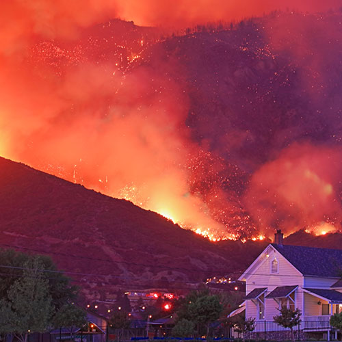
How Often Wildfires Occur
Wildfire activity in the United States has intensified significantly over the past decade. Longer fire seasons, hotter temperatures and drier conditions have contributed to more frequent, fast moving and severe wildfire events across both rural and urban communities within the wildland-urban interface (WUI) area.
The identified WUI area continues to expand by approximately two million acres per year – increasing the number of homes and critical facilities exposed to wildfire hazards and highlighting the growing need for proactive mitigation and resilient construction practices.
Wildfire Related Losses
More than 46 million homes in 70,000 communities are at risk from wildfire in the WUI. This expanding exposure creates cascading impacts for housing availability, insurance markets, local economies and recovery timelines.
The National Interagency Fire Center (NIFC) National Significant Wildland Fire Potential Outlook (issued April 1, 2026) documented that as of March 31, 2026, 1,615,683 acres have burned nationally — 231 percent of the previous ten-year average — with 16,746 wildfires reported (also above average).
Additionally, over the past 15 years, wildland fires have destroyed more than 100,000 structures in the U.S., with 70 percent of these losses occurring since 2018.
The cost of wildfire includes structural losses, infrastructure damage, business interruption, environmental impacts and long term health consequences from smoke exposure.

Losses Avoided Through Building Codes and Mitigation
Mitigation remains one of the most effective tools for reducing wildfire risk and long term costs. Communities that adopt and enforce modern construction codes experience significantly lower losses during hazard events. The International Wildland-Urban Interface Code® (IWUIC) is designed specifically to address the vulnerabilities that drive large-loss WUI disasters, including ember exposure, radiant heat and direct flame contact.
FEMA's Building Code Save: Fire Hazards Pilot Study estimates modern wildfire-related building codes produce billions in avoided losses over the useful life of homes in studied wildfire-prone areas.
Using the International Codes (I‑Codes) to Mitigate Wildfire Hazards
The International Codes® (I Codes®), including the 2024 IWUIC, provides a comprehensive framework for designing, constructing and retrofitting buildings to be more wildfire resilient.
The IWUIC establishes regulations to safeguard life and property from the intrusion of wildland fire and to help prevent structure fires from spreading to wildland fuels. It focuses on practical measures that reduce the likelihood of building ignition from embers, radiant heat and direct flame contact, and it is designed to be compatible with the full suite of I Codes.
The 2024 IWUIC addresses four broad areas:
- WUI Area Designation: Where the code applies after state/local WUI mapping or formal designation process
- Ignition-resistant construction: Building features and materials that reduce ignition risk, especially from embers
- Defensible Space and Vegetation Management: Requirements for managing fuels near structures to reduce wildfire intensity
- Access, Water Supply and Fire Protection: Community provisions that support firefighting operations, including access, water supply and fire protection
Key Wildfire Provisions
Click book cover below to reveal/hide code sections.

International Wildland Urban Interface Code®
Chapter 1 – Scope and Administration
Chapter 1 establishes the administrative framework for applying the IWUIC when adopted by a state or jurisdiction. It addresses scope, administration and how the adoption - such as whether appendices are enforceable - is activated through an adopted ordinance and the authority of the code official.
Key IWUIC references: Chapter 1, including Section 101.2.1 (Appendices).
Key terms (defined in Chapter 2): Scope, Applicability, Code official/authority, Permits, Construction documents, Approved agency, Alternative materials or methods, Appeals.
Chapter 2 – Definitions
Chapter 2 provides definitions used throughout the IWUIC. These definitions support consistent interpretation and enforcement of WUI area designations, defensible space, ignition-resistant construction and fire protection concepts across the code.
Key IWUIC references: Chapter 2, including Sections 201 (General) and 202 (Definitions).
Key terms (defined in Chapter 2): Wildland-urban interface area, Wildfire, Defensible space, Fire hazard severity, Ignition-resistant construction, Fuel (light/medium/heavy).
Chapter 3 — Wildland-Urban Interface Areas
Chapter 3 explains how WUI areas are identified so a community can determine where IWUIC requirements apply. It supports both mapped and procedure-based designation approaches and provides a basis for documenting designations and updates over time.
Key IWUIC references: Sections 301 (General) and 302 (WUI area designations), including Sections 302.2 (Mapping) and 302.3 (Review of WUI areas).
Key terms (defined in Chapter 2): Wildland-urban interface area, Wildland, Mapping of wildland-urban interface area, Wildland-urban interface area designations, Findings of fact, Fire hazard severity, Fire hazard severity form.
Chapter 4 — Wildland-Urban Interface Area Requirements
Chapter 4 addresses site and development requirements for projects in designated WUI areas. The provisions focus on enabling safe and effective fire service operations by addressing access and related infrastructure considerations which are often coordinated with local fire department standards.
Key IWUIC references: Sections 401 (General) through 405 (as applicable), including Sections 402.1.1 (Access), 403.2 (Driveways), and 403.3 (Fire apparatus access road).
Key terms (defined in Chapter 2): Access, Driveways, Fire apparatus access road, Address markers, Subdivision, Service utilities, Water supply, Fire flow calculation area.
Chapter 5 — Special Building Construction Regulations
Chapter 5 focuses on how buildings can better resist wildfire exposures. It provides ignition-resistant construction concepts and requirements based on identified severity level intended to reduce susceptibility to ignition, with emphasis on common ignition pathways such as embers and exposure to heat and flame.
Key IWUIC references: Sections 501 (Scope) and 503 (Ignition-Resistant Construction and Material).
Key terms (defined in Chapter 2): Ignition-resistant construction (Classes 1–3), Ignition-resistant building material, Noncombustible, Roof assembly, Roof covering, Noncombustible roof covering, Fire-retardant-treated lumber or wood, Multilayered glazed panels, Flame spread index.
Chapter 6 — Fire Protection Requirements
Chapter 6 addresses wildfire-related fire protection measures that complement site and construction provisions. It includes topics such as automatic suppression provisions (where applicable), fuel modification concepts, defensible space maintenance, and fire protection considerations for hazards and equipment commonly present in WUI settings.
Key IWUIC references:Selected sections include 602.1 (Automatic sprinkler systems), 603.2 (Fuel modification), 604 (Defensible space/maintenance), and 606 (Liquefied petroleum gas installations).
Key terms (defined in Chapter 2): Automatic sprinkler systems, Defensible space, Maintenance of defensible space, Fuel modification, Fuel modification distance, Vegetation control, Vegetation management plan, LP-gas installations, Storage of firewood and combustible materials, Spark arrestors.
Chapter 7 — Referenced Standards
Chapter 7 lists the external standards that are referenced by the IWUIC. When a state or jurisdiction adopts the IWUIC, these referenced standards become part of the compliance framework for IWUIC provisions that rely on test methods, product standards and installation criteria.
Key IWUIC references: Chapter 7 (Referenced Standards).
Key terms (defined in Chapter 2): Referenced standards, Approved, Approved agency, Listed (as applicable), Inspection and enforcement.
Appendices (Optional—Apply Only When Adopted)
Appendices provide supplemental tools and provisions that a state or jurisdiction may choose to adopt. Their applicability depends on adoption language (see Section 101.2.1).
- Appendix A — General Requirements
Appendix A provides supplemental fire protection measures that support wildfire risk reduction, including vegetation control, ignition source controls, storage practices and protection of water supply equipment. It can be adopted to supplement Chapter 6 where a jurisdiction wants additional operational and preventive measures.
Key IWUIC references: Appendix A, including Sections A101 (General) and A102 (Vegetation control).
Key terms (defined in Chapter 2): Vegetation control, Ignition source control, Control of storage, Hazardous materials, Protection of pumps and water storage facilities, Temporary structures and uses.
- Appendix B — Vegetation Management Plan
Appendix B provides a framework for preparing a vegetation management plan when required. It helps document the actions, methods and schedules that will be used to manage fuels and defensible space in a way that is clear, repeatable and maintainable.
Key IWUIC references: Appendix B, including Sections B101.1 (Scope) and B101.2 (Plan content).
>Key terms (defined in Chapter 2): Vegetation management plan, Defensible space, Fuel mosaic, Fuel-loading, Fire-resistive vegetation.
- Appendix C — Fire Hazard Severity Form
Appendix C provides a form-based tool that jurisdictions may use to document fire hazard severity considerations. This can support consistent determination and communication of wildfire exposure and severity classifications in local implementation.
Key IWUIC references: Appendix C, including Section C101.1 and Table C101.1 (as applicable).
Key terms (defined in Chapter 2): Fire hazard severity, Fire hazard severity form, Critical fire weather, Slope.
- Appendix D — Fire Danger Rating System
Appendix D provides a structured fire danger rating approach that can support operational decisions during periods of heightened wildfire risk. When adopted, it can help guide restrictions or heightened precautions in WUI areas during critical fire weather.
Key IWUIC references: Appendix D (Fire Danger Rating System).
Key terms (defined in Chapter 2): Fire danger rating system, Fire danger rating, Critical fire weather.
- Appendix E — Findings of Fact
Appendix E provides a findings-of-fact framework that can support documentation for WUI designations and other determinations where a documented basis is needed. It helps create transparent, repeatable decision-making processes.
Key IWUIC references: Appendix E (Findings of Fact).
Key terms (defined in Chapter 2): Findings of fact, Mapping, Wildland-urban interface area designations.
- Appendix F — Characteristics of Fire-Resistive Vegetation
Appendix F provides information on characteristics associated with fire-resistive vegetation. It can be used as guidance when evaluating landscaping and vegetation choices that contribute to reduced ignition potential near structures.
Key IWUIC references: Appendix F (Characteristics of Fire-Resistive Vegetation.
Key terms (defined in Chapter 2): Fire-resistive vegetation, Trees, Tree crown.
- Appendix G — Self-Defense Mechanism
Appendix G provides alternative concepts that jurisdictions may use as an implementation tool for communities and property owners to help protect exposed structures. Where used, it can help organize protective actions and increase options for structure preparedness.
Key IWUIC references: Appendix G (Self-Defense Mechanism).
Key terms (defined in Chapter 2): Self-defense mechanism, Emergency access, Fire weather.
- Appendix H — IWUIC Flowchart
Appendix H provides a flowchart-style navigation aid intended to help users understand the application of the IWUIC. It may support consistent application and communication of requirements based on fire hazard severity.
Key IWUIC references: Appendix H (International Wildland-Urban Interface Code Flowchart).
Key terms (defined in Chapter 2): Flowchart, Applicability, Compliance alternatives.
Wildfire Resources
Preparedness
Emergency Planning
Visit Ready.gov for emergency planning, evacuation preparation, alerts and household readiness resources for wildfire events.
National Trends
For current conditions and national trends, see the National Significant Wildland Fire Potential Outlook from the National Interagency Fire Center (NIFC).
Response
Stay Safe
Learn how to stay safe during and after a wildfire. Follow evacuation orders, avoid smoke exposure and stay informed through local emergency alerts.
Recovery
Rebuilding Resiliency
Rebuilding with the I-Codes and IWUIC helps communities recover stronger, reduce future wildfire losses, and create a more resilient future for residents, businesses, and critical infrastructure.
Pairing Mitigation with Local Recovery
When communities begin recovering after a wildfire, it’s essential to rebuild with future resilience in mind. Local governmental leaders, recovery committees and planning groups can integrate mitigation into every recovery decision by using established assessment methods, such as state and local hazard mitigation plans and applying a multi-hazard approach to rebuilding.
Use wildfire mitigation plans as roadmaps
Reference state or local hazard mitigation plans to guide decisions on where and how recovery projects should be designed, funded and implemented.
Conduct post‑wildfire damage & risk assessments
Evaluate the extent of damage, identify recurring problem areas and document vulnerabilities to inform mitigation‑focused rebuilding.
Embed mitigation in all recovery discussions
Ensure that community town hall meetings, planning meetings and community workshops include mitigation options as part of every proposed solution.
Prioritize multi‑hazard strategies
Consider community hazards and risks beyond wildfires (e.g. flooding, tornado, earthquakes, etc.) and pursue solutions that reduce exposure to multiple hazards at once.
Leverage recovery funding for mitigation
Explore opportunities within federal, state and local disaster assistance funding programs that allow or encourage mitigation as part of repair and reconstruction.
Rebuild with resilience
Encourage use of ignition-resistant materials, installation methods and infrastructure designs that address long‑term risk.
Engage the community
Involve residents, businesses and local organizations to ensure mitigation measures reflect community needs and support long‑term resilience.
Flood Mitigation
Flooding is one of the most frequent and costly natural hazards in the United States, affecting homes, businesses, community infrastructure and critical services. From riverine floods to flash flooding and coastal storm surge, these events disrupt homes and businesses and can create long‑term consequences for local economies.
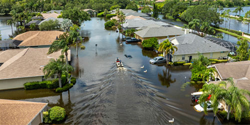

How Often Flooding Occurs
Deadly floods swept through the United States at a record pace in 2025, triggering more flash flood warnings than any year to-date. Additionally, between 2020 and 2023, the United States experienced 80 major flood disasters, a rate that represents nearly half of the previous decade’s total.
Annual Flood‑Related Losses
Recent analysis estimates that flooding now costs the U.S. between $179.8 and $496 billion annually, equivalent to 1–2% of the U.S. GDP. These losses include infrastructure damage, business interruption, residential property losses and far‑reaching economic impacts.
Losses Avoided Through Building Codes and Mitigation
Mitigation through code adoption and implementation is one of the most cost‑effective strategies communities can use to reduce long‑term flood impacts and insurance costs.
Federally funded riverine flood mitigation projects produce a 7:1 benefit‑cost ratio, meaning $7 saved for every $1 spent.
Using the International Codes (I‑Codes) to Mitigate Flood Hazards
The International Codes® (I‑Codes®) provide a comprehensive framework for designing, constructing and retrofitting buildings to be more flood‑resilient. Excerpts of the flood-resistant provisions from the 2024 I-Codes, including a summary of changes to flood provisions from the 2021 to 2024 editions, can be accessed here.
Key Flood Provisions
Click book cover below to reveal/hide code sections.
International Existing Building Code®
Chapter 1 Scope and Administration
- Section 104 Duties and Powers of Code Official
- 104.2.4.1 Flood hazard areas. Only under certain extraordinary circumstances can the code official grant modifications to provisions related to flood resistance for repairs, alterations or additions to existing buildings located in flood hazard areas that constitute substantial improvement.
- 104.3.1 Determination of substantially improved or substantially damaged existing buildings and structures in flood hazard areas. The code official is required to determine if proposed work on existing buildings located in flood hazard areas constitutes substantial improvement or repair of substantial damage. Where the code official determines that the proposed work constitutes substantial improvement or repair of substantial damage, the building is required to meet the requirements of the IBC or the IRC as applicable.
- Section 109 Inspections
- 109.3.3 Lowest floor elevation. For additions and substantial improvements to existing buildings in flood hazard areas, after placement of the lowest floor and prior to vertical construction, documentation related to the elevation of the lowest floor is to be submitted to the code official.
- 109.3.10 Flood hazard documentation. For additions and substantial improvements to existing buildings in flood hazard areas, prior to the final inspection, documentation related to the elevation of the lowest floor or the elevation of dry floodproofing is to be submitted to the code official.
Chapter 2 Definitions
These definitions provide a common language for designing buildings to resist severe wind events. While the IEBC incorporates the definitions found in the International Building Code® (IBC), those terms that are unique to existing buildings can be found within Chapter 2 of the IEBC.
DANGEROUS
EXISTING BUILDING
EXISTING STRUCTURE
FLOOD HAZARD AREA
HISTORIC BUILDING
LOWEST FLOOR
REPAIR
RISK CATEGORY
STORM SHELTER
SUBSTANTIAL DAMAGE
SUBSTANTIAL IMPROVEMENT
SUBSTANTIAL STRUCTURAL ALTERATION
SUBSTANTIAL STRUCTURAL DAMAGE
UNSAFE
Chapter 3 Provisions for All Compliance Methods
- Section 301 Administration
- 301.3 Alteration, addition or change of occupancy. This section provides the code official with the authority to allow alterations that comply with the laws in existence at the time the building was built, unless the alterations constitute substantial improvement in a flood hazard area. When the alterations constitute substantial improvement in a flood hazard area all work is required to comply with Sections 503.2, 701.3 or 1303.1.3.
Chapter 4 Repairs
- Section 401 General
- 401.3 Flood hazard areas. In flood hazard areas, repairs that constitute substantial improvement shall require that the building comply with the IBC or the IRC as applicable.
- Section 405 Structural
- 405.2.6 Flood hazard areas. In flood hazard areas, buildings that have sustained substantial damage shall be brought into compliance with the IBC or the IRC as applicable.
Chapter 5 Prescriptive Compliance Method
- Section 502 Additions
- 502.2 Flood hazard areas.For buildings in flood hazard areas, any addition that constitutes substantial improvement of the existing building is required to comply with the flood design requirements for new construction, and the balance of the existing building is to be brought into compliance with the flood requirements for new construction.
For buildings in flood hazard areas, any addition that does not constitutes substantial improvement of the existing building is not required to comply with the flood design requirements for new construction, provided the addition does not violate flood-resistant construction requirements and the lowest floor of the addition is constructed at or above the lower of the lowest floor of the existing building.
- Section 503 Alterations
- 503.2 Flood hazard areas. For buildings in flood hazard areas, any alteration that constitutes substantial improvement of the existing building is required to comply with the flood design requirements for new construction, and the balance of the existing building is to be brought into compliance with the flood requirements for new construction.
For buildings in flood hazard areas, any alteration that does not constitutes substantial improvement of the existing building is not required to comply with the flood design requirements for new construction.
- Section 507 Historic Buildings
- 507.3 Flood hazard areas. For Historic buildings that meet certain criteria and located in flood hazard areas, any work that constitutes substantial improvement of the existing building is not required to comply with the flood design requirements for new construction.
Chapter 7 Alterations — Level 1
- Section 701 General
- 701.3 Flood hazard areas. In flood hazard areas, alterations that constitute substantial improvement are required to comply with the IBC or the IRC, as applicable.
Chapter 11 Additions
- Section 1103 Structural
- 1103.3 Flood hazard areas. This section addresses additions within flood hazard areas that are required to comply with specific requirements. These requirements are based on whether the addition is structurally interconnected or independent of the existing building. The requirements are also based on whether the addition is a vertical addition atop an existing building or atop its own foundation.
Chapter 12 Historic Buildings
- Section 1201 General
- 1201.4 Flood hazard areas. For Historic buildings that meet certain criteria and located in flood hazard areas, any work that constitutes substantial improvement of the existing building is not required to comply with the flood design requirements for new construction.
Chapter 13 Performance Compliance Methods
- Section 1303 Acceptance
- 1303.1.3 Compliance with flood hazard provisions. If the work covered by this section is a structurally connected horizontal addition that does not constitute substantial improvement, the addition is not required to comply with the flood design requirements for new construction, provided the addition does not violate flood-resistant construction requirements and the lowest floor of the addition is constructed at or above the lower of the lowest floor of the existing building.
Chapter 14 Relocated or Moved Buildings
- Section 1402 Requirements
- 1402.6 Flood hazard areas. If an existing building is relocated into a flood hazard area, the building is required to comply with the IBC or the IRC, as applicable.
International Residential Code®
Chapter 1 Scope and Administration
- R106.1.4 Information for construction in flood hazard areas: Addresses delineation of flood hazard areas, elevation of lowest floor and lowest horizontal structural member, etc.
- R109.1.3 Floodplain inspections: Elevation documentation to be prepared and sealed by a registered design professional shall be submitted upon placement of the lowest floor prior to vertical construction.
Chapter 3 Building Planning
- R306.1 Flood-resistant construction: Requires buildings located in flood hazard areas be designed and built in compliance with Section R306. Buildings located in floodways shall be designed and constructed with ASCE 24(2014).
- R306.2.1 Elevation requirements: Flood hazard areas, not including Coastal A Zones, shall have the lowest floors (including basement floors) at or above the base flood elevation plus one foot, or the design flood elevation, whichever is higher.
International Building Code®
Chapter 1 Scope and Administration
- 104.2.4.1 Flood hazard areas: Limits the building official’s ability to grant modifications in flood hazard areas.
- 107.2.6 Site plan: Site plans are required in the construction documents for permitting. Flood hazard areas, floodways and design flood elevations shall be indicated on site plans as applicable.
- 110.3.3 Lowest floor elevation: Requires elevation certification in flood hazard areas.
- 110.3.12.1 Flood hazard documentation: Requires documentation of the elevation of the lowest floor or the elevation of dry floodproofing, if applicable.
Chapter 16 Structural Design
- 1612.2 Design and construction: Requires that the design and construction of buildings and structures located in flood hazard areas shall be in accordance with Chapter 5 of ASCE 7 and ASCE 24.
- 1612.3 Establishment of flood hazard areas: Requires the applicable governing authority shall adopt flood hazard map and supporting data.
- 1612.4 Flood hazard documentation: Requires that documentation shall be prepared and sealed by a registered design professional and submitted to the building official for construction in flood hazard areas and coastal high hazard areas
Appendix G Flood-Resistant Construction
- Intended to provide the additional flood-plain management and administrative requirements of the National Flood Insurance Program.
- Adoption of the IBC and Appendix G will meet the minimum requirements of NFIP as set forth in Title 44 of the Code of Federal Regulations.
Flood Resources
Preparedness
Emergency Planning
Visit Ready.gov for emergency planning, supplies lists, alerts, evacuation prep and household readiness resources for flooding events.
Training for Officials
When Disaster Strikes Institute’s Substantial Damage Estimates and Determinations, Building Safety Evaluator, and Coordinator training courses teach field teams, team leaders and managers to efficiently and consistently assess post-flood damage.
Response
Stay Safe
Learn how to stay safe during and after a flood. Evacuate if told to do so, move to higher ground or a higher building floor and stay where you are.
Training for Officials
When Disaster Strikes Institute’s Evaluator Training and Coordinator Training courses teaches evaluators, team leaders and managers to safely and effectively assess and inspect post‑flood structures.
Recovery
Evaluation for Safety
The Substantial Damage Evaluation process is required by FEMA as part of the NFIP. This process determines whether a building is Substantially Damaged thereby requiring compliance with current flood-resistant code requirements.
Training for Officials
The 2024 IBC/IRC/IEBC have updated definitions and relocated Substantial Improvement and Substantial Damage terminology to support consistency, enforcement and compliance.
Pairing Mitigation with Local Recovery
When communities begin recovering after a flood, it’s essential to rebuild in ways that reduce future risk. Local governmental leaders, recovery committees and planning groups can integrate mitigation into every recovery decision by using established assessment methods, such as state and local hazard mitigation plans and through applying a multi‑hazard approach to rebuilding.
Use hazard mitigation plans as roadmaps
Reference state or local hazard mitigation plans to guide decisions on where and how recovery projects should be designed, funded and implemented.
Conduct post‑flood damage & risk assessments
Evaluate the extent of damage, identify recurring problem areas and document vulnerabilities to inform mitigation‑focused rebuilding.
Embed mitigation in all recovery discussions
Ensure that community town hall meetings, planning meetings and community workshops include mitigation options as part of every proposed solution.
Prioritize multi‑hazard strategies
Consider community hazards and risks beyond flooding (e.g. wildfire, earthquakes, etc.) and pursue solutions that reduce exposure to multiple hazards at once.
Rebuild with resilience
Encourage use of flood‑resistant materials and infrastructure redesigns that address long‑term risk.
Leverage recovery funding for mitigation
Explore opportunities within federal, state and local disaster assistance funding programs that allow or encourage mitigation as part of repair and reconstruction.
Engage the community
Involve residents, businesses and local organizations to ensure mitigation measures reflect community needs and support long‑term resilience.
Essential Fire Safety Provisions
The technical basis for safer and more resilient buildings in lower resource contexts
A fundamental resource that includes the essential principles of fire protection into a practical guide for authorities, inspectors, firefighters, architects and engineers.

View Book

Contact ICC Global Solutions
“It is a great endeavor, which offers the option for the adoption of prescriptions that have already been widely tested in terms of their results”
Eng. Alejandro Ramirez, Chile
“We can include a large part of this document in the fire regulations of my country”
Eng. José Joaquín Álvarez, CFPS, Colombia
“This document is very comprehensive and applicable to Latin America and the Caribbean”
Eng. Luis Cestari, PE, World Bank
“For an architect like me working in fire code regulation, this document is what I have tried to achieve”
Arch. Alejandro Flores, CFPS, Mexico
Testimonials
View more thoughts from our stakeholders
Benefits for Jurisdictions and Organizations
- Strengthening life security
- Improved design and build quality
- Reduction of risks and economic losses
- Greater consistency in the application of requirements
- Technical basis for the adoption of modern codes
International Alignment
The publication is aligned with the principles and objectives of:
- International Code Council (ICC)
- International Building Code (IBC)
- International Fire Code (IFC)
It supports resilience, sustainable development, and institutional strengthening initiatives in lower resource contexts.
Key Book Content
The publication clearly and practically addresses essential issues such as:
- Classification of occupations
- Types of construction and fire resistance
- Means of Egress
- Fire Protection Systems
The content is organized for ease of use in both daily work and training programs.
Drive safer buildings in your jurisdiction or organization.
Find out how Essential Fire Safety Provisions can become the technical foundation for improving safety, resilience, and professional capability in your community.
Also available en español
Testimonials
"It's very well organized... very useful and easy to understand for professionals and technicians who may use it"
– Arch. Lourdes Giusti, CFPS – Peru
"It is a great endeavor, which offers the option for the adoption of prescriptions that have already been widely tested in terms of their results"
– Eng. Alejandro Ramirez, Chile
"This fire code fills a big gap in Latin America"
– Eng. Emmanuel Reyes, CFPS, Dominican Republic
"This is the way to address the great challenges of the region"
– Eng. Carlos Halke, Paraguay
"We can include a large part of this document in the fire regulations of my country"
– Eng. José Joaquín Álvarez, CFPS, Colombia
"This document is very comprehensive and applicable to Latin America and the Caribbean"
– Eng. Luis Cestari, PE, World Bank
“For an architect like me working in fire code regulation, this document is what I have tried to achieve"
– Arch. Alejandro Flores, CFPS, Mexico
"This document is a dream come true"
– Eng. Jaime A. Moncada, PE, Editor
"EFSPI is going to be a very relevant milestone"
– Eng. Andrés Mayobre, CFPS, Uruguay
"The topics included in this document are on point and of great importance"
– Eng. Alonso Umaña, CFPS, Costa Rica
"Even if it is applied voluntarily in a project, it is an excellent design tool"
– Eng. Donato Pirro, CFPS, Panama
Aspectos Esenciales de Seguridad Contra Incendios
La base técnica para edificaciones más seguras y resilientes
Un recurso fundamental en español que traduce los principios esenciales de Seguridad contra incendios en una guía práctica para autoridades, inspectores, bomberos, arquitectos e ingenieros.
Ver la publicación

Capacitación
Contactar a Soluciones Globales ICC
“Corresponde a un gran esfuerzo ofrecer una opción de adopción de prescripciones ya ampliamente probadas en términos de sus resultados”
Ing. Alejandro Ramírez, Chile
“Podemos incluir gran parte de este documento en la normativa de incendios de mi país”
Ing. José Joaquín Álvarez, CFPS, Colombia
“Este documento es muy completo y aplicable a Latinoamérica y el Caribe”
Ing. Luis Cestari, PE, World Bank
“Para un arquitecto como yo, trabajando en el desarrollo de códigos, este documento es lo que había tratado de lograr”
Arq. Alejandro Flores, CFPS, México
Testimonios
Conozca más opiniones de nuestros colaboradores.
Beneficios para Jurisdicciones y Organizaciones
- Fortalecimiento de la seguridad de vida
- Mejora de la calidad del diseño y la construcción
- Reducción de riesgos y pérdidas económicas
- Mayor consistencia en la aplicación de requisitos
- Base técnica para la adopción de códigos modernos
Alineación Internacional
La publicación está alineada con los principios y objetivos de:
- International Code Council (ICC)
- Código Internacional de la Edificación (IBC)
- Código Internacional de Protección contra Incendios (IFC)
Apoya iniciativas de resiliencia, desarrollo sostenible y fortalecimiento del cumplimiento normativo.
Contenido Clave del Libro
La publicación aborda de manera clara y práctica temas esenciales como:
- Clasificación de ocupaciones
- Tipos de construcción y resistencia al fuego
- Medios de egreso
- Sistemas de protección contra incendios
- Ocupaciones especiales y usos mixtos
El contenido está organizado para facilitar su uso tanto en el trabajo diario como en programas de capacitación.

Impulse edificios más seguros en su jurisdicción u organización.
Descubra cómo Aspectos Esenciales de Seguridad Contra Incendios puede convertirse en la base técnica para mejorar la seguridad, la resiliencia y la capacidad profesional en su comunidad.
También disponible en Ingles
Testimonios
“Está muy bien organizado… de mucha utilidad y fácil comprensión para los profesionales y técnicos que la usen”
Arq. Lourdes Giusti, CFPS – Perú
“Corresponde a un gran esfuerzo ofrecer una opción de adopción de prescripciones ya ampliamente probadas en términos de sus resultados”
Ing. Alejandro Ramírez, Chile
“Este código de incendios llena un gran vacío en Latinoamérica”
Ing. Emmanuel Reyes, CFPS, República Dominicana
“Atendiendo a los grandes desafíos de la región, este es el camino”
Ing. Carlos Halke, Paraguay
“Podemos incluir gran parte de este documento en la normativa de incendios de mi país”
Ing. José Joaquín Álvarez, CFPS, Colombia
“Este documento es muy completo y aplicable a Latinoamérica y el Caribe”
Ing. Luis Cestari, PE, World Bank
“Para un arquitecto como yo, trabajando en el desarrollo de códigos, este documento es lo que había tratado de lograr”
Arq. Alejandro Flores, CFPS, México
“Este documento es un sueño hecho realidad”
Ing. Jaime A. Moncada, PE, Editor
“El AESCI va a ser un hito muy relevante”
Ing. Andrés Mayobre, CFPS, Uruguay
“Los temas incluidos en este documento son muy acertados y de gran importancia”
Ing. Alonso Umaña, CFPS, Costa Rica
“Aun si se aplica de manera voluntaria en un proyecto, es una excelente herramienta de diseño”
Ing. Donato Pirro, CFPS, Panamá
Information & Advocacy
The International Code Council's (ICC) Fire and Disaster Mitigation (FDM) team has compiled resources to assist code officials, fire service professionals and community stakeholders in informed decision‑making, professional collaboration and effective implementation of strategies that strengthen resilience across the built environment.
This page includes information on ICC's Fire Service Membership Council, broader community engagement opportunities, key informational documents on emerging issues and a selection of reputable stakeholder organizations.





Find our more about or Stakeholder Organizations.
Fire Service Membership Council
The Fire Service Membership Council (FSMC) is a forum for concerns and issues that are of particular interest to the fire service. The FSMC facilitates the engagement of ICC members and stakeholders in the discussion and activities of interest to the fire service within the built environment. Members are encouraged to participate in ICC’s code development process, and to advise ICC on programs and policies, legislative matters, code adoption issues and such other matters as the FSMC deems appropriate. The FSMC is led by a Governing Committee comprised of fire officials from across the country, who guide the direction and activities of the FSMC.

Membership Qualifications
Membership in the FSMC is open to any individual who wishes to affiliate with the Fire Service Membership Council and is a member of ICC, an ICC Governmental Member Voting Representative, or employed by a jurisdiction or corporate member of ICC or a member in good standing of a closely aligned organization as approved by the ICC Board of Directors.
Join the FSMC
To join the FSMC, ICC members may access their myICC account and visit the FSMC site on ICC’s Member Community to sign up. Interested stakeholders or any general questions about the FSMC may be directed to Fire and Disaster Mitigation Program Manager Christine Reed. FSMC meeting information and general updates can be found on the ICC Member Community.
FSMC Governing Committee Members
Timothy Diehl, Howard County, MD; (IAFC: E); FSMC Chair
Doug Nelson, Bismarck, ND; (NASFM); FSMC Vice Chair
Bryan Adams, Pleasant Valley, OH
Ted Black, State of UT (NASFM)
Justin Sherwood, Bemidji, MN; (IAFC: GL)
Darcy Davidson, Carlsbad, CA
Michael Desrochers, State of VT
William Hyde, Rogers, AR (IAFC:SW)
Edward Kaminski, Clark County, NV
Kevin Lefebrve, Nisku, AB Canada (IAFC:C)
Jonathan Lund, Des Moines, IA; (IAFC:MV)
Larry Medina, State of OR (IAFC:W)
Kelly Nicolello, Fort Worth, TX
Brandon Sullivan, Colorado Springs, CO
Brendan O'Sullivan, Durham, NH (IAFC:NE)
Jon Davine, Stow, MA (NASFM)
Craig Landolt, Atlanta, GA (NASFM)
Sean Toomey, Concord, NH; ICC BOD Liaison
Karl Fippinger, Washington, DC; FSMC Staff Liaison
Christine Reed, Brea, CA; FSMC Staff Liaison
FSMC Governing Committee Meeting Schedule
The FSMC Governing Committee meets monthly and is open to all FSMC members and interested parties.
Virtual meetings take place on the third Thursday of each month at 1:30 pm ET (excluding in-person meetings). Meeting information, including the virtual meeting link, is listed in the Events section of the ICC Member Community.
Two in-person meetings are held annually in conjunction with the ICC Leadership Week in April and the ICC Annual Conference in October. These meetings are also open to all, and the meeting dates are listed on each event schedule.
Member Community
ICC's state-of-the-art Member Community is a free exclusive benefit offered only to ICC members. It's a self-service tool where building safety professionals can connect and network with other members, streamline communication and collaboration, create and share events and more.
The ICC Member Community App is now available on both Apple and Android devices. This powerful new tool puts a community of building safety professionals and a wealth of knowledge right at your fingertips. Learn more and download, here.
For any questions, please email membercommunity@iccsafe.org.


Stakeholder Organizations

International Association of Fire Chiefs (IAFC) represents the leadership of firefighters and emergency responders worldwide and provides leadership to current and future career, volunteer, fire-rescue and EMS chiefs, chief fire officers, company officers and managers of emergency service organizations throughout the international community.

The International Association of Firefighters (IAFF) is one of the largest and most influential labor unions in North America and is committed to advancing the rights, safety and future of fire fighters, emergency medical workers and rescue workers across the United States and Canada.

The National Volunteer Fire Council (NVFC) is the leading nonprofit membership association representing the interests of the volunteer fire, EMS, and rescue services. The NVFC serves as the voice of the volunteer in the national arena and provides critical resources, programs, education, and advocacy for first responders across the nation.

The U.S. Fire Administration supports and strengthens the fire and emergency medical services to prepare for, prevent, mitigate, and respond to all hazards.

Congressional Fire Services Institute (CFSI) educates members of Congress about the needs and challenges of the United States’ fire and emergency services to help them understand how the federal government can support the needs of local first responders.

National Association of State Fire Marshals NASFM’s mission is two-fold: To protect human life, property and the environment from fire, and to improve the efficiency and effectiveness of State Fire Marshals’ operations.

The Fire Safety Research Institute (FSRI) advances fire safety knowledge to address the world’s unresolved fire safety risks and emerging dangers. FSRI shares fire safety insights with everyone to advance UL’s public safety mission of providing safe living and working environments for people everywhere.

The National Institute of Standards & Technology (NIST) was founded in 1901 and is one of the nation's oldest physical science laboratories. Through its focus on buildings and construction, fire testing has been a cornerstone of NIST’s research. Its Disaster & Failure Studies Program assesses building performance in the wake of disasters and failure events.

Society of Fire Protection Engineers (SFPE) mission is to define, develop and advance the use of engineering best practices, expand the scientific and technical knowledge base, and educate the global fire safety community, to reduce fire risk

Insurance Institute for Business & Home Safety (IBHS) is an independent nonprofit scientific research and communications organization supported by property insurers, reinsurers, and affiliated companies. IBHS’s building safety research leads to real-world solutions for home and business owners, helping to create more resilient communities.

The Federal Emergency Management Administration (FEMA) mission is helping people before, during and after disasters. FEMA leverages a tremendous capacity to coordinate within the federal government to make sure America is equipped to prepare for and respond to and recover from disasters.

National Emergency Management Association (NEMA) provides national leadership and expertise in comprehensive emergency management, serves as a vital emergency management information and assistance resource, and advances continuous improvement in emergency management through strategic partnerships, innovative programs and collaborative policy positions.

The International Association of Emergency Managers (IAEM) is a non-profit educational organization dedicated to promoting the "Principles of Emergency Management" and representing those professionals whose goals are saving lives and protecting property and the environment during emergencies and disasters.

The Association of State Floodplain Managers is a 501(c)(3) scientific and educational nonprofit organization dedicated to reducing flood loss in the United States.
Building Safety Month
Building Safety Month is an international campaign held each May to raise awareness about the importance of safe building practices within the built environment. Everyone can play a role in enhancing building safety and reducing fire risks by supporting Building Safety Month initiatives.
The campaign features weekly themes, including one dedicated to practical safety tips for homes. Topics include fire prevention and awareness, smoke alarms and fire sprinklers, water and pool safety, disaster preparedness and electrical hazard awareness, with actionable strategies for each to help increase safer living spaces.
For more information on Building Safety Month and resources for fire safety at home, click here.
 .
.
Stay informed with essential industry updates and expert technical insights from the award-winning Building Safety Journal. Explore hundreds of free articles, including Batteries and ESS, Disaster Preparedness and Fire & Wildland Urban Interface-related content.
The Building Safety Journal (BSJ) Weekly is a free weekly newsletter from the International Code Council that compiles the latest news on the building safety and construction sectors, including fire-related news and updates, and is delivered to your inbox on Thursdays. Subscribe, here.
Training, Education and Certification
The International Code Council's (ICC) Fire and Disaster Mitigation (FDM) Team is committed to equipping professionals with the latest knowledge and practical skills to prevent, mitigate and respond to disasters effectively.
Below you'll find information on fire service and emergency management educational tracks, certifications and training materials to help you stay current with evolving codes and standards.

Fire Service & Emergency Management Educational Tracks
The International Code Council’s (ICC) Fire & Disaster Mitigation (FDM) Team is developing structured and comprehensive training tracks to support fire and emergency management professionals at every stage of their careers. These tracks will offer clear progression from foundational skills to advanced leadership, ensuring that professionals are equipped to protect communities and implement safety codes effectively.

Plan Review
Essential training for fire plans examiners to review construction documents, identify compliance issues and apply the latest fire and life safety requirements.

Inspections
Foundational training for fire inspectors, focusing on core skills such as code interpretation, field inspections and documentation.

Fire Marshal
Advanced curriculum for fire marshals, including leadership development, program management, community risk reduction strategies and technical expertise.

Disaster Mitigation/ Response
Training for building and fire code officials involved in disaster mitigation, preparedness, response and recovery.

Specialty & Hot Topics
Explore emerging and specialized areas in fire and disaster mitigation. These five tracks are designed to address evolving challenges and technologies.
- Battery Energy Storage Systems (BESS)
- Code Adoption & Legislative Process
- Fire & Life Safety Systems
- Hazardous Materials
- Wildland-Urban Interface (WUI)
Certifications
Why Get Certified?
ICC certifications are a globally-recognized mark of excellence. They validate technical expertise, enhance professional credibility and demonstrate commitment to public safety.
Benefits of Certification
- Career Advancement: Certifications open doors to promotions, specialized roles and leadership positions.
- Credibility: Gain recognition from peers, employers and jurisdictions around the world.
- Community Impact: Certified professionals play a vital role in reducing risk and improving safety in their communities.

Explore ICC Fire Code Certifications
- Fire Inspector I (66)
- Fire Inspector II (67)
- Fire Plans Examiner (F3)
- Fire Code Specialist
(combination designation) - Fire Marshal (combination designation)
- Commercial Fire Alarm Inspector
- Commercial Fire Sprinkler Inspector
- Commercial Fire Alarm Plans Examiner I
- Commercial Fire Alarm Plans Examiner II
- Commercial Fire Sprinkler Plans Examiner
- Residential Fire Sprinkler Plans Examiner
CEUs and Renewals
Maintain your ICC credentials with continuing education opportunities. ICC offers a variety of CEU-eligible courses to help you stay current with evolving codes and standards.
Reciprocal/Transition Certifications
ICC recognizes certifications from other professional organizations, allowing for streamlined transitions and cross-recognition.
Partner Organizations
- ProBoard (Fire Inspector I and Fire Inspector II)
- State of California (CA to ICC and ICC to CA)
- NCPCCI
Training Materials
Live/Online Training Courses
Participate in expert-led sessions available in both virtual and in-person formats. These courses cover essential topics in fire safety, inspections and emergency response.
Self-Guided Study Courses
Learn at your own pace with structured programs designed to help you prepare for certification exams and deepen your understanding of fire codes.
Study Guides & Materials
Access code-specific references, practice exams and support tools to help you prepare for exams effectively.
Online Learning Subscription
Join ICC code experts every Wednesday for 90-minute ICC Learn Live sessions covering a wide range of code topics.